
Traditional machine operations like lathes, milling, and drilling have historically relied heavily on manual control, leading to reduced accuracy and precision and requiring significant human effort and time. In response to these challenges, computer numerically controlled (CNC) machines were created. These machines are programmed in advance, enabling automatic operation and decreasing human involvement, thus enhancing precision.
CNC machines are sophisticated pieces of equipment designed to automate the manufacturing of parts using various materials, including metal, plastic, and wood. While CNC machines can be found in different configurations, the most common ones are CNC mills and CNC lathes. CNC lathes are specifically well-suited for manipulating cylindrical parts, while mills can be utilized for flat, curved, or angular components.
CNC machines consist of several key components and elements that contribute to their functionality and efficiency. Here, we will explore the primary parts of CNC machines and the elements they incorporate.
Parts of a CNC Machine
This section aims to provide an overview of the various components found in CNC machines. While certain parts such as the control unit, driving system, and feedback system are shared between lathes and mills, there are also specific elements unique to each type of machine. For instance, tailstocks and headstocks are exclusive to CNC lathes.
The key components of a CNC machine include:
1. The Input Device
The input device of a CNC machine is responsible for loading CNC programs into the system. This device can take the form of a keyboard, allowing users to input G-code commands directly. Alternatively, it can involve a USB flash drive for transferring completed programs from another computer, or wireless communication for downloading programs from a connected computer through the local network.
2. Machine Control Unit (MCU)
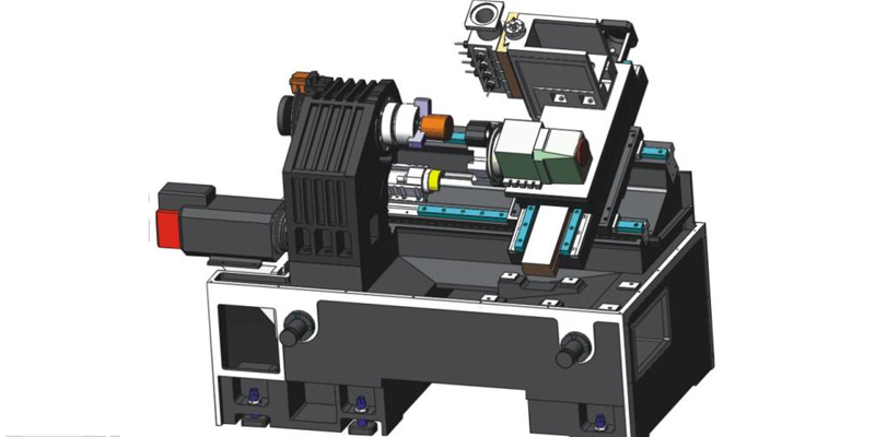
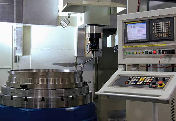
The machine control unit (MCU) is a crucial electronic hardware and software component of a CNC machine. Its role is to read the supplied G-code and translate it into instructions that the tool drivers can execute to perform the required machining operations. The MCU is responsible for interpreting G-code coordinates, which in turn, dictate the movements carried out by servo motors across different machine axes. Additionally, the MCU utilizes feedback sensors to ensure that the tool is accurately positioned after each movement is completed. It also manages tool changers and activates coolant systems as specified within the G-code. Figure 1 depicts a typical control unit configuration.
3. Control Panel
The control panel of a CNC machine incorporates various components to facilitate operator interaction. It typically consists of an input device, a display unit, a keyboard, and additional control buttons. To provide flexibility, the control panel is often attached to the CNC machine using an extendable arm. This allows the operator to position the screen in a convenient location for easy access and operation.
4. The Drive System
The drive system consists of motors responsible for moving the tool along the various axes of the CNC machine. In a standard CNC mill, the bed is horizontally moved along the x- and y-axes, while the cutting tool moves vertically along the z-axis. While in a standard CNC lathe, the drive system moves the cutting tool in alignment with the axis of workpiece rotation. The cutting tool is introduced to the outer diameter of the material along the rotational axis of the workpiece as opposed to across it. The movement in a CNC machine is commonly controlled by linear guides, servo motors, and ball screws. Servo motors precisely move the ball screw nut to position different mechanical components, such as the spindle and the bed. Linear guides ensure that the movement of the bed and spindle is accurate and minimizes any potential play or deviations.
5. Machine Tools
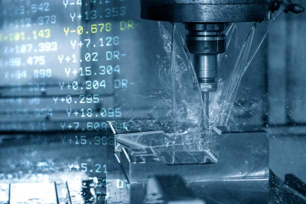
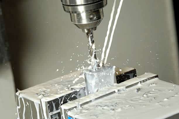
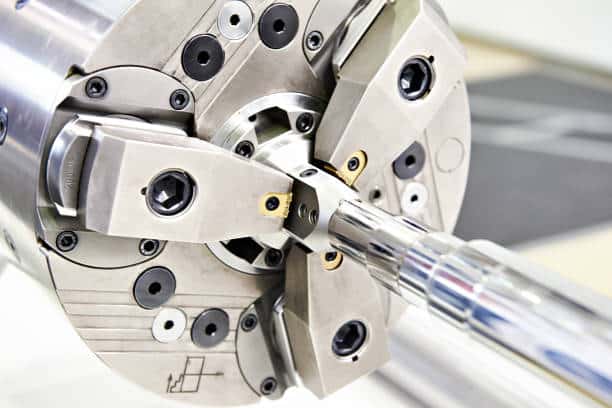
The term “machine tools” refers to various tools used to perform processes on workpieces, typically involving cutting. The specific form of machine tools varies depending on the type of CNC machine. CNC lathes utilize stationary tools and move the rotating raw material into the tool for cutting. CNC mills, on the other hand, move rotating tools into stationary material for cutting. However, more advanced 5-axis machines have the capability to move both the tool and the workpiece, enabling the creation of more intricate features in the final part. Machine tools are often stored in “tool libraries,” which are racks designed to hold all the necessary tools for machining a part. The tool changer is responsible for automatically removing a tool from the spindle, placing it back in the tool library, and replacing it with the next required tool. Figure 2 illustrates a typical machine tool configuration for a CNC mill.
6. Feedback Mechanism
Despite the precise nature of the drive system, it is often necessary to incorporate a closed-loop control system. This ensures that after the machine moves a mechanical component to a specific position, the position is verified and, if needed, adjusted. To measure the position, linear or rotary encoders are commonly used. These encoders are attached to the servo motors and provide feedback on the actual position of the components.
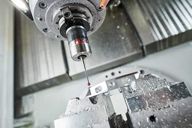
Additionally, special probing tools are utilized to zero the machine and measure the actual part during machining. This allows for potential adjustments to the machining parameters to fulfill dimensional requirements. Figure 3 showcases a typical probing tool configuration.
7. Headstock
The headstock is a distinct component found in lathes. It includes the primary drive, bearings, and gears necessary to rotate the chuck at the specified speeds for machining operations. Typically located on the left-hand side of a CNC lathe, the headstock is usually enclosed and can be accessed through removable inspection panels.
8. Bed
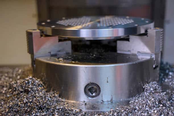
The bed of a CNC mill serves as the mounting platform for the raw material. To secure the workpiece in place, various work-holding jigs are utilized. The bed is often equipped with t-slots or holes that allow for the attachment of these jigs. In conventional CNC machines, the bed facilitates movement solely along the horizontal x- and y-axes. However, more advanced 5-axis machines can incorporate rotational motions along the x- and y-axes as well. Figure 4 depicts an example of a part mounted on the bed of a CNC mill.
In the case of a CNC lathe, the tool turret and the tailstock are secured to the bed, while the chuck holds the raw material.
9. The Tailstock
The tailstock is an essential component of a CNC lathe that provides axial support to long cylindrical workpieces. It works alongside the chuck, which supports and rotates the material. The tailstock plays a crucial role in preventing the material from deflecting away from the cutting tool due to the forces generated during the cutting process. The raw material is centered on the tailstock quill, which rotates freely within the tailstock. This component is particularly useful for cutting shafts or power screws. Its movement is restricted to the lathe’s z-axis, allowing for accommodating different lengths of raw material.
10. Tailstock Quill
Situated within the tailstock, the tailstock quill features a conical end that aligns with the spindle and chuck axis. When machining a long shaft, a blind hole is often drilled at the center of the workpiece’s end so that the quill can be positioned to provide support. The quill has a limited range of motion. The tailstock is brought close to the part, and then the quill is activated using pneumatic or hydraulic pressure to securely hold the raw material in place.
11. Footswitch or Pedal
Footswitches or pedals are utilized in CNC lathes to activate and deactivate the chuck and tailstock quill. These pedals provide convenience for operators to load blanks onto the machine and unload completed parts. However, CNC mills do not typically utilize foot pedals as the parts are already supported on the bed, and operators do not require both hands-frees while loading and unloading raw material.
12. Chuck
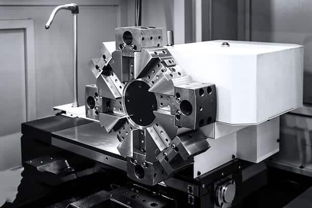
A chuck is an integral component specifically designed for lathes. Its primary function is to securely grip the raw material during machining. The chuck is driven by the spindle and rotates at high speeds. Typically, a chuck consists of three or four grips that can be actuated pneumatically or hydraulically. Three-jaw chucks are self-centering, as all the grips move radially simultaneously. Conversely, four-jaw chucks allow for individual grip adjustments and are not self-centering. Four-jaw chucks offer greater accuracy compared to three-jaw chucks and enable eccentric cutting, as the grip positions can be precisely controlled to accommodate variations in the raw material. Refer to Figure 5 for a visual representation of a typical three-jaw chuck.
13. Display Unit
The display unit serves as a screen that provides important information to the operator. It can come in various forms, including large high-resolution screens that display a wide range of information, or small low-resolution screens that only show essential details. The display unit enables the operator to interact with different functions of the CNC machine, such as inputting G-code or modifying machine settings. Furthermore, it provides real-time information on the current operating status of the machine.
Elements of a CNC Machine
A CNC machining system typically comprises several key components as follows:
Program
The program serves as the computer input and is typically entered using a keyboard. It instructs the machine to perform specific functions or execute the provided control codes. These control codes are divided into two sets: G-codes and M-codes.
The Common Codes Used In CNC Programming
| Code | Explanation of Code |
| N | Sequence Number |
| G | Rapid Traverse |
| X, Y, Z | For tool motion about X, Y, and Z direction (Linear Motion) |
| S | Spindle Speed (Unit as per your setting) |
| F | Feed Rate |
| T | Tool Number (i.e. Tool number 1 for facing or turning) |
| M | Miscellaneous Functions |
| EOB | End of Block (End of the program) |
| A, B, C | For angular direction in X, Y, and Z direction |
G-codes are used to command the machine on specific movements, such as machining operations and tool paths. On the other hand, M-codes refer to miscellaneous machine commands that do not involve axis movements.
Machine Control Unit (MCU)
The main control of a CNC machine, often referred to as the mini-computer or machine control unit (MCU), plays a crucial role in managing various machine functions. Its primary functions include:
- Initiating or stopping the machine’s spindle
- Automatically adjusting the spindle speed
- Controlling the direction of spindle rotation
- Starting or stopping the supply of coolant
- Regulating the feed rate or adjusting the workpiece
- Changing tools as required
In addition to these functions, a mini-computer also offers the advantage of diagnostic software. This software helps detect issues or problems with the computer and facilitates the restoration process.
Servo System
The primary function of the servo system is to receive control signals from feedback devices and adjust the output accordingly to control various components of the CNC machine, such as shafts and tools.
The servo system is composed of the following main components:
- Feedback devices: These devices provide information on the position and movement of machine parts. They help the servo system accurately determine the current state of the machine.
- Servo motors: These motors receive control signals from the feedback devices and generate the necessary torque and speed to move the machine components precisely.
- Ball screws: Ball screws are utilized to transmit the rotational motion of the servo motor into linear motion, allowing for precise movement of the machine parts.
Tape Reader
In both CNC machining and injection molding, a tape reader is utilized as a storage device for storing specific machining programs. These programs can be easily modified, allowing for convenient editing of the current program based on the requirements of the machining process.
How Does a CNC Machine Work?
A CNC machine operates by utilizing CAD and CAM programs along with computer control. CAD (Computer-Aided Design) software is employed for drawing purposes. It not only enhances the productivity of designers but also improves design quality, facilitates communication through documentation, and creates a manufacturing database.
On the other hand, CAM (Computer-Aided Manufacturing) involves programming operations using two code sets: G-code and M-codes. These codes are utilized to create programs that are fed into the CNC machine to perform various operations, such as turning or grooving in a lathe.
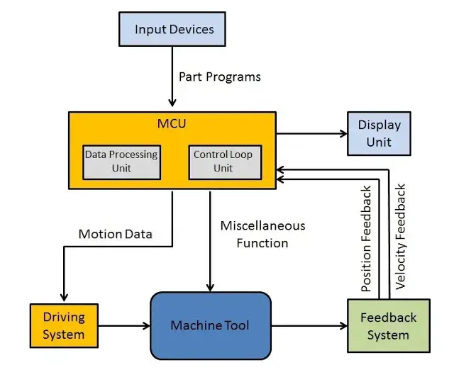
Here are the brief steps involved:
- Firstly, write and insert the part program, consisting of G and M codes, into the Machine Control Unit (MCU) of the CNC machine.
- The data is then processed, and commands are generated based on the program. These commands are sent to the driving system.
- The drive system receives the motion commands from the MCU and controls the movement and velocity of the machine tool.
- A feedback system is in place to record the position and velocity measurements of the machine tool. It sends feedback signals back to the MCU.
- The MCU compares the feedback signals with reference signals and corrects any errors detected. It then sends new signals to ensure the machine tool operates correctly.
- A display unit is utilized as the visual interface, allowing operators to view commands, programs, and other vital data. It functions as the “eye” of the machine.
What Is a CNC Machine?
A CNC (computer numerical control) machine is an automated tool that operates under computer control. It is capable of shaping a variety of materials, including metals, plastic, or wood, based on instructions generated through CAM (computer-aided manufacturing) software. Two commonly utilized types of CNC machines are CNC lathes and CNC mills.
Advantages of Using a CNC Machine
Manufacturers have greatly benefited from the use of CNC machines, as they contribute to heightened productivity, improved accuracy, and reduced human error by automating manual production operations. The impact of CNC machines on engineering and manufacturing can be summarized in four key ways:
- Exceptional precision and accuracy
CNC machines are known for their high precision. The typical tolerance for CNC machining is +/- 0.127mm. However, with the use of a tolerance configurator, you can achieve even greater precision, down to +/- 0.005mm. This level of accuracy demonstrates just how precise CNC machining can be. - Ideal for making large-volume parts
CNC machining is an excellent choice for manufacturing a large number of parts. When producing mechanical components in quantities ranging from double digits to the hundreds of thousands, CNC machining is often the most cost-effective option compared to 3D printing. - Versatile to machine various materials
CNC machines have the versatility to work with various materials. Unlike 3D printing, which primarily focuses on plastics, CNC machines can handle a wider range of materials. At Runsom Precision, we carefully select the appropriate material for each project, and we offer over 60 production-quality materials for CNC machining. Commonly used metals include aluminum, stainless steel, magnesium alloy, zinc alloy, titanium, and brass. - Fast production capabilities and turnarounds
It’s indisputable that machines can operate much faster than humans. When you source your CNC machined components from a reliable CNC machine shop, you can expect quick turnaround times, with the final products delivered in as fast as 5 days.
Disadvantages of Using a CNC Machine
While CNC machines are widely utilized, it is essential to acknowledge their drawbacks.
One notable disadvantage is their high cost. CNC machines are considerably more expensive when compared to manual machines. However, their high production rates and ability to spread costs over a larger sales volume can help recoup the initial investment.
Furthermore, operating CNC machines requires skilled labor, which can be expensive. In cases where small, simple, or one-off parts need to be machined, using a manual machine may be more cost-effective and faster. The programming and setup required for custom parts on a CNC machine may not always be economically viable in such scenarios.
What’s the Difference between a CNC and NC Machine?
NC, short for numerical control, refers to an automated machine that operates based on binary, numeric, or alphanumeric programs.
An NC machine is comprised of the following components:
- Software: The programming software is responsible for generating the instructions that the machine will follow.
- MCU (Machine Control Unit): The MCU acts as the control center for the NC machine, interpreting the program instructions and directing the machine’s movements.
- Machine Tools: These are the physical tools and equipment used by the NC machine to perform various operations.
Unlike CNC machines, NC machines lack a servo mechanism, which means they do not have a feedback system. Additionally, NC machines do not have a computer. The program is typically stored on a tape using a special inserting device. Modifying or making changes to the program can be a challenging task with an NC machine.
The table below summarizes the main differences between the NC machine and the CNC machine:
| NC Machine | CNC Machine |
| NC refers to a type of machine with numeric control | CNC refers to a type of machine with computer numerical control |
| It doesn’t operate based on software | It’s software-driven |
| It can not import CAD files | It imports CAD files and converts them into part programming |
| Operation parameters cannot be altered | Operation parameters are adjustable |
| It stores in punch cards memory | It stores directly in computer memory |
| It cannot run continuously | It can run continuously for 24 hours |
| It lacks flexibility and computational power | It boasts high flexibility and computational ability |
| It has longer execution times for programs | It takes less time for executing the program |
| It requires high-skilled operators | Semi-skilled operators can operate CNC machines |
| It requires less maintenance scheduling | It requires frequent maintenance scheduling |
| Lower maintenance costs | Higher maintenance costs |
| Lower machining costs | High machining costs |
| Lower accuracy | Higher accuracy |
| The codes consist of numbers, symbols, and letters exclusively | The codes are G and M codes |
| A single person cannot operate multiple NC machines for various tasks | A single person can operate multiple CNC machines for various tasks |
| There is no feedback mechanism | There is a feedback mechanism |
Applications of a CNC Machine
CNC machines have become integral to the manufacturing industry, with their usage prevalent across various sectors. The increasing competitiveness and growing demands have led to a significant rise in the adoption of CNC machines. These machines encompass a range of machine tools such as lathes, mills, drillers, and welding equipment.
Multiple industries have embraced the use of CNC machines, including the automotive industry, medical industry, optical industry, energy industry, metal removal industries, metal fabrication industries, and electrical discharge machining industries, to name a few.
Conclusion
This post provided comprehensive information about CNC machines, including their components, functions, applications, limitations, and advantages.
To further explore the capabilities of CNC machines, we recommend reaching out to a representative from Runsom Precision. Runsom Precision offers a diverse range of manufacturing services, including CNC machining services and other value-added services, to cater to your prototyping and production requirements. Visit our website to gather more information or to request an instant online quote.
Other Articles You May Be Interested in: