

Engineering drawing abbreviations are a set of standardized symbols and abbreviations used on engineering drawings to represent common terms and phrases. The symbols and abbreviations represent various components, processes, and measurements used in engineering design. Abbreviations are used to reduce the amount of text required to convey the same information on a drawing. These abbreviations can be found on engineering drawings such as mechanical, electrical, piping and plumbing, civil, and structural drawings. Common abbreviations include AC (alternating current), DC (direct current), FAB (fabrication), and LD (load).
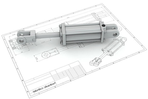
As an integral part of CAD/CAM technology, CNC design is used to develop and produce products. However, engineering drawings are complex as they are full of symbols and abbreviations that you might not understand. Here we provide a complete guide to standard engineering drawing abbreviations and symbols for your reference.
Why Abbreviations and Symbols Are Needed for Engineering Drawing?
Abbreviations and symbols are used in engineering drawings to save time, improve accuracy and clarity, increase standardization, simplify complex information, and reduce costs. They provide a quick and efficient way of conveying detailed information without having to write out lengthy descriptions, which helps to ensure that all parts and details are accurately specified and understood by everyone involved in the engineering project. Standardization of abbreviations and symbols across the engineering industry makes it easier to communicate between engineers and other professionals, and helps to reduce the amount of time and effort required to create engineering drawings. Its functions can be included below:
- To save time and space: Abbreviations and symbols are used in engineering drawings to conserve space and time. They provide a quick way of communicating information without having to write out lengthy descriptions.
- To improve accuracy and clarity: Abbreviations and symbols are used to ensure that all parts and details are accurately specified and understood by everyone involved in the engineering project.
- To increase standardization: Abbreviations and symbols are standardized across the engineering industry, which allows for more efficient communication between engineers and other professionals.
- To simplify complex information: Abbreviations and symbols are used to simplify complex information, making it easier for engineers and other professionals to understand what is being conveyed in the drawing.
- To reduce costs: Abbreviations and symbols reduce the amount of time and effort required to create engineering drawings, decreasing costs associated with a project.
How to Read Symbols in An Engineering Drawing?
Technical standards are the definition and glossary of abbreviations, symbols, and acronyms that may be found on engineering drawings. International Engineering Standards may be different from countries and applications applied, like International (ISO), USA (AISI, ANSI, ASTM, SAE, AMS), UK (BS), France (AFNOR), Germany (DIN, WR), Australia (AS), Sweden (SS), Korea (KS). Note that the same abbreviation may represent different meanings in different types.
Once you understand the meaning and definition of the symbols and abbreviations, you’ll pick up and use the engineering drawing with ease. An engineering drawing often tells the specific requirements and detail, such as:
- Finish
- Tolerances
- Dimensions
- Hardware
- Geometry
- Material type
Engineering Drawing Abbreviations
The charts below are a complete list of abbreviations and symbols in engineering drawings. All the lists provided below are in alphabetical order for easy reference, you can use this as a guide to help you understand your engineering drawing.
A
| AC | across corners |
| AF | across flats |
| AFF | above finished floor |
| AISI | American Iron and Steel Institute |
| Al or AL | aluminium |
| ALY | alloy |
| AMER | American |
| AMS | Aerospace Material Standards |
| AN- | Army-Navy |
| ANN | anneal, annealed |
| ANSI | American National Standards Institute |
| APPROX | approximately |
| AQL | acceptable quality level |
| AR | as required |
| AS | Aerospace Standards; Australian Standards |
| AS, APS, APV, AV, APSL, AVL | approved product supplier, approved vendor, approved-product-supplier list, approved-vendor list |
| ASA | American Standards Association |
| ASME | American Society of Mechanical Engineers |
| ASSY or ASY | assembly |
| ASTM | Formerly the American Society for Testing and Materials; now ASTM International |
| AVG | average |
| AWG | American Wire Gauge |
B
| BASIC | basic dimension |
| BC or B.C. | bolt circle |
| BCD or B.C.D. | bolt circle diameter |
| BHC | bolt hole circle |
| BHCS | button head cap screw |
| BHN | Brinell hardness number |
| BoM or BOM | bill of materials |
| BoP or BOP | bought out part |
| BP, B/P | blueprint |
| BRZ | bronze |
| BSC | basic dimension |
C
D
| depth, deep, down | |
| ⌀ | diameter |
| D | diameter; delta |
| DIA | diameter |
| DIP | ductile iron pipe |
| DIM | dimension, dimensioning |
| DO, do | ditto |
| DOD, DoD | [U.S.] Department of Defense |
| DPD | digital product definition |
| DWG, dwg | drawing |
E
| ED | edge distance |
| EO, ECO, ECN | engineering order |
| EQL, EQ | equal, equally |
| ERC | electrical rule check |
| EXIST. | existing |
F
| f | finish |
| FAO | finish all over |
| FCF | feature control frame |
| FD or F/D | field of the drawing |
| FIM | full indicator movement |
| FL | flag note, flagnote |
| FL | Floor Level |
| FN or F/N | flag note, flagnote; find number |
| FoS | feature of size |
| FPSO | Floating Production Storage and Offloading |
| FS | far side |
| FSCM | Federal Stock/Supply Code for Manufacturers |
| FTG | fitting |
G
| GCI | gray cast iron |
| GD&T or GDT | geometric dimensioning and tolerancing |
| GN or G/N | general note(s) |
H
| HBW | hardness, Brinell, tungsten tip |
| HDPE | high-density polyethylene |
| HHCS | hex head cap screw |
| HRA | hardness, Rockwell, A scale |
| HRB | hardness, Rockwell, B scale |
| HRC | hardness, Rockwell, C scale |
| HRS | hot rolled steel |
| HT TR | heat treat, heat treatment |
| H&T or H/T or HT | hardened and tempered |
I
| IAW | in accordance with |
| ID | inner diameter; identity, identification number |
| IED | Insufficient Edge Distance |
| ISO | International Organization for Standardization |
J
| JIS | Japan Industrial Standard |
K
| KEY | key |
| KPSI, kpsi | kilopounds per square inch, that is, thousands of pounds per square inch |
| KSI, ksi | kilopounds per square inch, that is, thousands of pounds per square inch |
L
| LDD | limited dimension drawing |
| LH | left-hand |
| LM or L/M | list of materials |
| LMC | least material condition |
M
| MACH | machine; machined |
| MAJ | major |
| MAX | maximum |
| MBD | model-based definition |
| MBP | measurement between pins |
| MBW | measurement between wires |
| MF or M/F | make from |
| MFD | manufactured |
| MFG | manufacturing |
| MFR | manufacturer |
| MIL- | [U.S.] Military |
| MIN | minimum; minutes; minor |
| MMC | maximum material condition |
| MOD, MoD | Ministry of Defence [U.K. and others] |
| MOP, MoP | measurement over pins |
| MOW, MoW | measurement over wires |
| MPa, MPA | megapascals |
| MRB | material review board |
| MS- | [U.S.] Military Standard |
N
| NAS | National Aerospace Standards |
| NC | National Coarse; numerical control |
| NCM | nonconforming material(s) |
| NCR | nonconformance report |
| NEC | not elsewhere classified; National Electrical Code |
| NEF | National Extra Fine |
| NF | National Fine |
| NL or N/L | notes list |
| NOM | nominal |
| NORM or NORMD | normalized |
| NPS | Naval Primary Standard[3] |
| NPT | National Pipe Taper |
| NS | National Special; near side |
| NSCM | National Stock/Supply Code for Manufacturers |
| N&T or N/T or NT | normalized and tempered |
| NTS | not to scale |
O
| OAL | overall length |
| OC | on center(s) |
| OD | outer diameter |
| ODA | original design activity |
| OHL | over high limit |
| OPP | opposite |
| ORIG | original |
P
| pc, pcs | piece, pieces |
| PD | pitch diameter |
| PDM, PDMS | product data management, product data manager [app], product data management system [app] |
| PH or P/H | precipitation hardening, precipitation-hardened; pilot hole |
| PHR BRZ | phosphor bronze |
| PL or P/L | parts list |
| PLM | product lifecycle management; plant lifecycle management |
| PMI | Product and manufacturing information |
| PN or P/N | part number |
| POI | point of intersection |
| P.F. | press fit |
| PSI | pounds per square inch |
| PTFE | polytetrafluoroethylene |
| PVC | polyvinyl chloride |
Q
| QMS | quality management system |
| QTY or qty | quantity |
R
| R | radius |
| RA, Ra | roughness, average; Rockwell A scale |
| RB, Rb | Rockwell B scale |
| RC, Rc | Rockwell C scale |
| REF | reference dimension |
| REQD or REQ’D | required |
| REV | revision |
| RFS | regardless of feature size |
| RH | right-hand |
| RHR | roughness height reading |
| RL | Reduced Level or Relative Level |
| RMA | return material authorization |
| RMS | root mean square |
| RT or R/T | rough turn, rough turned; room temperature |
| RTP | release to production |
| RTV | room-temperature vulcanizing; return to vendor |
| RZ, Rz | roughness, mean depth |
S
| SAE | Formerly the Society of Automotive Engineers; now SAE International |
| SC or S/C | sharp corners |
| SF or S/F | spotfaceslip fit |
| SFACE or S/FACE | spotface |
| SHCS | socket head cap screw |
| SHN | shown |
| SHSS | socket head set screw |
| SI | Système international [d’unités] [International System of Units] |
| SN or S/N | serial number |
| SOL ANN | solution anneal, solution annealed |
| SPEC or spec | specification |
| SPHER ANN | spheroidize anneal |
| SPOTFACE | Spot facing |
| SR | spherical radius |
| SS or S/S | stainless steel; supersede |
| SST | stainless steel |
| STD | standard |
| STEP | Standard for the Exchange of Product Model Data |
| STA | solution treated and aged |
| STI | screw thread insert |
| STL | steel |
| STK | stock |
| SW | Schlüsselweite |
T
| TAP | tapped hole |
| TB or T/B | title block |
| TCC | time-current curve |
| TDP | technical data package |
| THD or thd | thread |
| THRD | threaded |
| THK or thk | thickness |
| THRU | through |
| THRU ALL | Through all |
| TIR | total indicator reading; total indicated run-out |
| TOS | top of steel |
| TOL | tolerance, tolerancing |
| TSC | theoretical sharp corner(s) |
| TY | type |
| TYP | Typical |
U
| UAI | use as-is |
| ULL | under low limit |
| UNC | Unified National Coarse |
| UNEF | Unified National Extra Fine |
| UNF | Unified National Fine |
| UNJC | Unified National “J” series Coarse |
| UNJF | Unified National “J” series Fine |
| UNO | unless noted otherwise |
| UNS | Unified National Special; unified numbering system |
| UON | unless otherwise noted |
| UOS | unless otherwise specified |
| USASI | United States of America Standards Institute |
| USS | United States Standard; United States Steel |
| UTS | ultimate tensile strength; Unified Thread Standard |
V
| v | finish |
W
| WC | tungsten carbide |
| WI | wrought iron |
| W/I, w/i | within |
| W/O, w/o | without |
X
| _X_ | used to indicate the word “by” |
| X or ( ) | number of places—for example, 8X or (8) |
Y
| Y14.X | — |
| YS | yield strength |
Common Engineering Drawing Abbreviations Used in CNC Machining
Although it’s easy to illustrate all the details in a design drawing for the manufacture of CNC milling parts or CNC turning parts, there is not enough space on a drawing to cover all the texts and images. The abbreviations and symbols are then designed to express the characteristics of the product. They are easy to be understood by people from any country in concise forms. Common engineering drawing abbreviations used for CNC machining are listed below:
| AC | Across corners |
| ALY | Aluminum |
| ANN | Anneal |
| AQL | Acceptable quality level |
| AR | As required |
| AVG | Average |
| BASIC or BSC | Basic dimension |
| BC or B.C. | Bolt circle |
| BHC | Bolt hole circle |
| BRZ | Bronze |
| CAD | Computer-aided design |
| CERT | Certification |
| CI | Cast iron |
| CNC | Computer Numerical Control |
| CRES | Corrosion-resistant |
| DIM | Dimension |
| ED | Edge distance |
| IAW | In accordance with |
| LMC | Least material condition |
| MBP | Measurement between pins |
| MBW | Measurement between wires |
| MFD | Manufactured |
| MFG | Manufacturing |
| MFR | Manufacturer |
| MMC | Maximum material condition |
| OAL | Overall length |
| PC | Piece |
| PD | Pitch diameter |
| PL | Parts list |
| PMI | Product and manufacturing information |
| REF | Reference |
| RZ | Roughness, mean depth |
| SFACE | Spotface |
| SN | Serial number |
| STD | Standard |
| UNC | Unified National Coarse |
| UNS | Unified National Special |
| YS | Yield Strength |
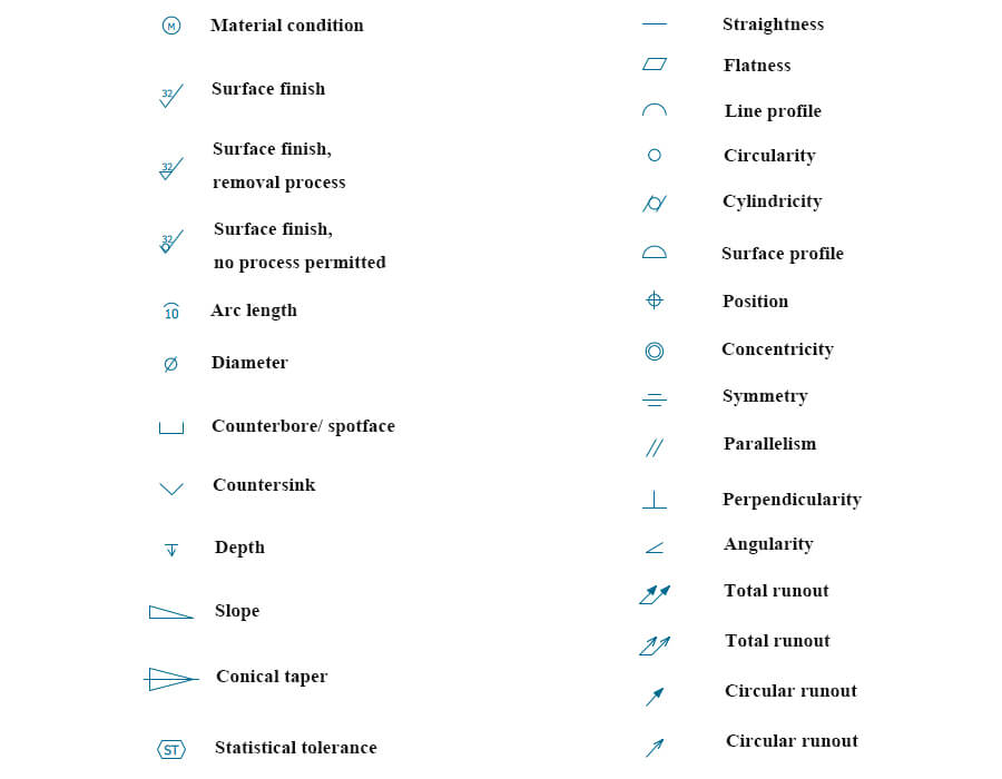
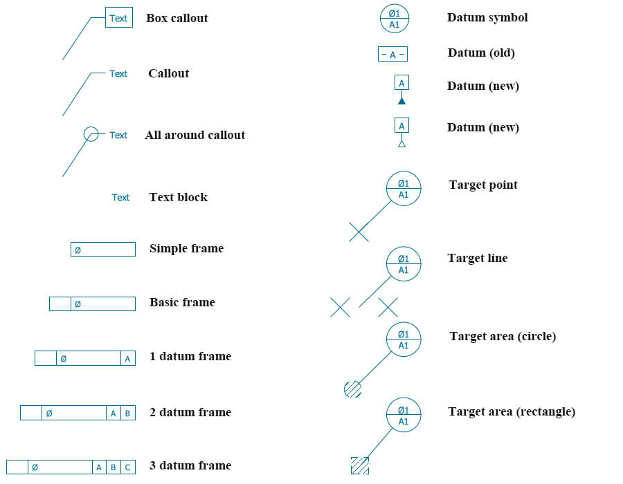
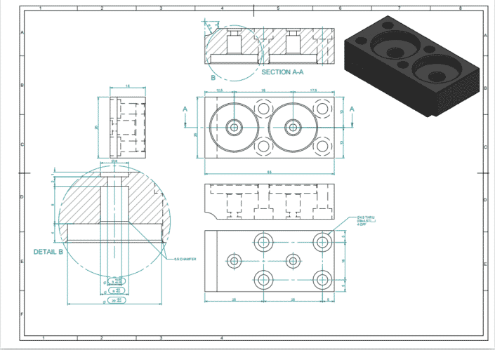
Engineering Drawing Symbols
The basic symbol types used in engineering drawings are diameter, depth, radius, counterbore, spotface, and countersink. The following are commonly used engineering drawing symbols and design elements.
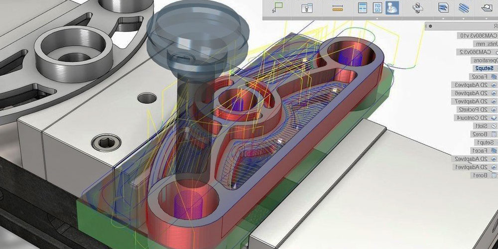
Work with Runsom for Your CNC Programming Projects
If your CNC programming projects are too complex for you, Runsom would be a premier choice. Our engineers are proficient with CNC programming, and have rich experience in the CNC machining field. If you have the demand, feel free to get an instant quote or contact us directly today!
Other Articles You May Be Interested in: