

Feeds and speeds are important parameters in CNC machining that directly affect the product quality, accuracy, and surface finish, as well as machining efficiency and tool life. But what factors affect these parameters, and how do you determine the optimum speed and feed for your machining process? This article is here to offer a detailed guide on speeds and feeds for CNC machining operations and explains how to calculate the optimal values.
Essential Terms Explained
When starting with the main body of this article, there are several important criteria you need to know:
- RPM: Revolutions per minute (RPM) is a measure of how fast a rotating object turns. This represents how fast your tool is rotating, but not how fast the flutes is moving.
- Feed rate: Feed rate is the speed at which the cutting tool moves relative to the workpiece, often measured in inches per minute (IPM).
- Feed per Tooth: Feed per Tooth is the rate at which the cutting tool moves into the material per tooth on the cutting tool, typically measured in inches per tooth (IPT).
- Surface Speed: Surface Speed is the speed at which the cutting tool is moving relative to the surface of the material being cut, typically measured in feet per minute (FPM). This parameter is crucial because a larger tool will cut at a lower RPM at the same speed as a smaller tool with a higher RPM.
- Width of Cut: Width of Cut, abbreviated as WOC or RDOC, is the distance the cutting tool travels across the face of the material. It controls how involved the tool diameter is in the cut and the width of the chip.
- Depth of Cut: Depth of Cut, shorted for DOC or ADOC, is the distance the cutting tool moves into the material. It controls the length of the flute and thus the height of the chip.
Speeds and Feeds in CNC Machining
Speeds and feeds concern different velocities of a cutting process. Cutting speed is the rate at which the cutting tool advances along the workpiece and is measured in Surface Feet per Minute (SFM). Spindle speed, on the other hand, is the rotational speed of the cutting tool or workpiece and is measured in Revolutions per Minute (RPM).
Getting started with a CNC requires knowledge of various parameters, such as speeds, feeds, chip load, depth of cut, etc., that dictate the machine’s performance. To achieve the best results, one must find the optimal combination of these parameters. Generally, it’s recommended that use high speed with a slow feed rate to produce smooth cuts. However, using an extremely high speed can lead to overheating and tool damage, while a very slow feed rate will increase cycle time and decrease productivity. Thus, setting the optimal value is of great significance to producing clean cuts with high productivity.
Speed parameters of a CNC machine can be divided into two types: spindle speed and cutting speed.
Spindle Speed
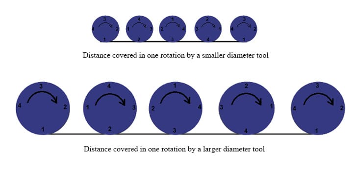
The difference between spindle speed and cutting speed is determined by the fact that two circles of different diameters, rotating at the same RPM, will cover different distances due to the larger circle having a larger circumference.
The spindle speed for a particular material is determined by the CNC machine, cutting tool, and type of material being machined. It is generally recommended to use a high RPM for soft materials and a low RPM for hard materials to maximize performance and tool life. However, running the material at too high or too low spindle speed can damage the workpiece and reduce tool life. Thus, it is best to select the optimal speed for the particular application.
Cutting Speed
Cutting speed is the relative speed between the workpiece and the cutting tool, which is calculated in terms of meters per minute (MPM) or surface feet per minute (SFM). This is the speed at which a particular point of the workpiece passes through the cutting edge and is used to measure the surface removed by the cutting teeth per minute.
Cutting speed is a key factor, along with feed rate and depth of cut, in determining the material removal rate (MRR) during machining. There is an optimum cutting speed for each material that is based on the material, cutting tool material, and expected tool life, which helps to ensure the accuracy provided by CNC machining.
The chart below exhibits optimal cutting speed of carbide end mill for different materials.
| Category | Materials | Cutting Speed (S.F.M) Under 32 HRC | Cutting Speed (S.F.M) Above 32 HRC |
|---|---|---|---|
| Cast Iron | Ductile Cast Iron | 100-400 | 100-200 |
| Gray Cast Iron | 100-400 | 80-140 | |
| High Temp Alloys | Cobalt Alloys | 60-100 | 40-80 |
| Nickel Alloys | - | 50-90 | |
| Iron Alloys | 80-130 | 60-120 | |
| Super Alloys | Titanium Alloys | 50-250 | 90-160 |
| Non-ferrous Materials | Aluminum, Aluminum Alloys | 800-2000 | 500-1000 |
| Copper | 800-1500 | 800-1000 | |
| Copper Alloys | 800-1000 | 700-1000 | |
| Magnesium | 1000 | 700-1000 | |
| Plastics, Acrylics, Phenolics | 200-800 | 200-500 | |
| Carbon, Graphites | 200-400 | - | |
| Steels | High Steel Strength | 50-250 | 80-180 |
| High Alloy Steels | 100-300 | 80-180 | |
| Medium Alloys Steels | 150-350 | 80-180 | |
| Low Alloy Steels | 100-400 | 100-200 | |
| Stainless Steel | Precipitation | 80-250 | 90-150 |
| Austenic | 100-350 | 100-150 | |
| Martensitic | 100-250 | 100-175 |
For more information, you can click this PDF – Selecting the Right Bit/Feeds and Speeds Charts for reference.
Feed Rate
Feed rate is the velocity at which a cutting tool is moved over a material in a single spindle revolution. It is represented in distance per revolution (DPR) units. It is determined by the RPM of the cutter, the chip load, and the number of flutes of the cutting tool. In general, a slow feed rate with a high RPM produces cleaner and smoother cuts, while a high feed rate may result in a rougher cut with a lower surface finish.
Factors Affecting Speeds and Feeds in CNC Machining
| Parameters | Relation with speed or feed |
| Spindle speed | Directly proportional to the feed rate |
| Number of flutes | Directly proportional to the feed rate |
| Chip load/Feed per tooth | Directly proportional to the feed rate |
| Cutting speed | Directly proportional to spindle speed |
| Tool diameter | Inversely proportional to spindle speed |
1. Cutting Tool Material
The cutting tool material affects its ability to withstand strong cutting forces. Carbide cutting tools can withstand greater forces than HSS tools and can be machined with faster speeds and feed configurations.
2. Tool Deflection
The deflection of the tool affects the quality of machining. A tool with a longer shank is susceptible to deflection under strong cutting force and cannot be used for high speeds and feeds configurations. A tool with a minimum stick-out has a small chance of deflection and can be used to deliver comparatively stronger forces.
3. Tool Diameter
Tool diameter is an important factor to consider when setting the optimal RPM for a machining process. A larger tool diameter can help complete the operation faster than a smaller one at the same RPM setting.
4. Cutting Teeth
The number of flutes (cutting teeth) of a tool is also an important factor in setting the optimal feed rate. A multi-flute cutter distributes the cutting force among all the flutes, reducing the risk of damaging the cutting tool and increasing the optimal feed rate.
5. Chip Load
Chip load, also referred to as feed per tooth, is the thickness of the chips removed during a machining process and is important for setting the optimal feed rate.
6. Workpiece Material
The type of material of the workpiece also affects the optimal speeds and feeds. Generally, hard materials require a slower feed rate than soft materials. Machining hard metals requires greater shearing force and a slow RPM and high-torque configuration. Soft materials, such as wood, require a high RPM to glide the cutting tool through the workpiece.
7. Stiffness of the Machine
The stiffness of the machine determines the maximum cutting force that can be transmitted to the workpiece. CNC machines with rigid chassis can provide stronger cutting forces.
Considerations for Cutting Speed in CNC Machining
Optimum cutting speed is essential to increase the efficiency of CNC machining. This is due to the fact that CNC machining is a software-controlled process, and the cutting speed depends on various factors. Some of the most important ones are the life of the tool, the type of lathe tool, and the material being used.
- Tool Life
Tool life is a fundamental factor in cutting speed considerations. Tool life basically refers to the period during which a cutting tool works effectively. Thus, the service life of the tool is essential in determining the cutting speed and accuracy of the workpiece. - Cutting Tool Material
Different types of lathe tools can be used with the CNC machine, and the strength of the cutting tool plays a role in the optimum cutting speed. For instance, the cutting tool made of high-strength material can be used for high-speed cutting, while cutting tools made of soft material can be used for low-speed cutting. - Workpiece Material
The material being used can be metals, wood, glass, etc., and the thickness and hardness of the material have an impact on the cutting tool and the cutting speed. If the material is too soft, then the cutting tool material will cut the material quickly with high accuracy and cutting speed, but for durable and harder materials, the cutting speed will be slow.
Considerations for Feed Speed in CNC Machining
Feed rate is an essential factor for achieving the desired finish of a workpiece. Machinists must consider a few factors when determining the optimal feed rate, such as the surface roughness, the cut width, the thread pitch on screws, and the type of tool being used for cutting the material.
- Surface Roughness of Workpiece
The feed rate increase with the growth of surface roughness. To get a smooth surface finish, the feed rate must be slowed down. - Cut Width
If the cut width is less than half the diameter, the chip may be thinned, causing manufacturing defects. Increasing the feed rate can help reduce this issue. - Thread Pitch
The feed rate is proportional to the thread pitch on screws being used. - Tool Types
The type of material being fed largely determines the type of tool used to cut material. So, the tool types used must fit the material being fed.
Calculations for Optimal Speeds and Feeds in CNC Machining Process
When determining the best speeds and feeds for a machining process, it is important to consult the reference catalog provided by the tool manufacturer for the optimal cutting speed (SFM).
Likewise, for a particular workpiece material, the optimum chip load for a cutting tool can also be gained from the manufacturer’s tool catalog.
To determine the optimal spindle speed and feed rate for different machining operations, the figures can then be used to perform the necessary calculations.
Calculations for Milling Operations

To calculate the optimal spindle speed for a CNC milling operation, you can use this equation:
S = (Vs x 12)/(π x D)
where S is the spindle speed in revolutions per minute (RPM), Vs is the cutting speed in surface feet per minute (SFM), and D is the diameter of the cutting tool in inches.
For metric units, you can calculate the spindle speed using the equation below:
S = (Vs x 1000)/(π x D)
Where Vs is the cutting speed in meters per second (m/sec) and D is the diameter of the tool in millimeters (mm).
To calculate the optimal feed rate (in inches per minute), you can use the following equation:
Feed Rate = Spindle Speed x Number of flutes x Chip load
The product of multiplying chip load with the number of flutes gives the cutting feed in inches per revolution (IPR). Therefore, feed rate (IPM) can also be calculated by multiplying spindle speed (RPM) and cutting feed (IPR).
Learn more about our CNC Milling capabilities
Calculations for Lathe Operations
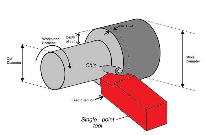
Machining operations on a CNC Lathe are distinct from other operations because instead of a spinning tool, lathe machines feature a rotating workpiece. As such, the lathe cutting tool is significantly different from router bits or end mills. Despite this, the speed and feed calculations for turning operations are quite similar to those of milling and drilling, with the only difference being the diameter taken into account for calculations.
Lathe machines feature a rotating workpiece, so the optimal spindle speed is calculated using the machined diameter of the workpiece instead of the tool diameter. The optimal spindle speed for a turning operation can be calculated using the following equation:
S = (Vs x 12)/(π x D)
Where S denotes the spindle speed in RPM, Vs denotes the cutting speed in SFM, and D denotes the cut diameter in inches. It is worth noting that the circumference of the workpiece or cutting tool is equal to the product of π and its diameter. Therefore, the spindle speed can also be expressed as the ratio of cutting speed at the tool-workpiece interface and its circumference.
Moreover, as lathe tools used for turning operations are mostly single-point cutting tools, the chip load is equivalent to the cutting feed per revolution (in inches per revolution).
Feed rate (IPM) = Spindle speed (RPM) x feed per revolution (IPR)
Learn more about our CNC Turning capabilities
Calculations For Drilling Operations
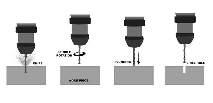
For drilling operations, the speeds can be calculated using the following formula:
S = (Vs x 1000)/(π x D)
where Vs is the cutting speed in meters per second (m/sec) and D is the diameter of the tool in millimeters (mm).
The feed rate is calculated by multiplying the spindle speed and the feed per revolution:
Feed rate (IPM) = Spindle speed (RPM) x feed per revolution (IPR)
Learn more about our CNC Drilling capabilities
Frequently Asked Questions (FAQ)
Depend on Runsom for Your CNC Machining Projects
By now, you may have a good understanding of the concept of cutting speed and feed rate in CNC machining, but it requires extensive skills and knowledge in actual practice. Why not just turn to an expert for your manufacturing demands? Runsom Precision, a specialist in the CNC machining industry, owns a team of highly skilled engineers and technicians who have rich experience in CNC machining operations and CNC programming. Reach out to us today to solve your machining matters or get an instant quote right now!
Other Articles You May be Interested in: