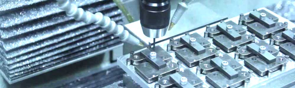

Key and keyway are commonly utilized for mechanical connections. In the process of machining mechanical parts, many long shaft parts are designed with multiple keyways. These keyways typically have strict requirements for dimensions, tolerance, and the angle between the keyway and the positioning reference hole. The ordinary marking method is insufficient to meet these needs. Moreover, shaft parts usually lack inadequate rigidity. As such, CNC milling machines are available for the processing of these components.
What type of cutter is used for milling keyways during the machining process? How to cut a keyway on a milling machine? In this article, we will provide an introduction to keyway milling, cover the fundamentals of keys and keyways, explore the cutters used in the operation, and discuss methods for milling keyways and alternatives to cut and broach keyways.
What is a Keyway?
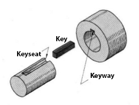
The key and keyway play a significant role when it comes to a gear or similar rotating equipment needing to be fitted onto a rod or shaft in order to transfer rotational force. The key is a mechanical transmission part primarily used for securing the circumferential connection between the shaft and the parts on the shaft to transmit torque. Some keys can also facilitate axial movement or axial fixation of the parts on the shaft. Keyways are grooves of various shapes that are cut along the axis of the cylindrical surface of the shafts. These grooves serve as the location for fitting the keys and provide a reliable method for positioning and driving members on the shafts. A keyway is also machined in the mounted member to receive the key.
The selection of the key type and corresponding keyway depends on the specific requirements of the task. The woodruff key, the square-ends machine key, and the round-end machine key are the most commonly used types of keys.
What is Keyway Milling?
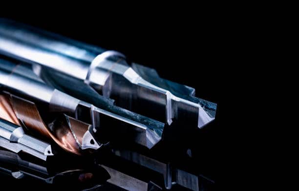
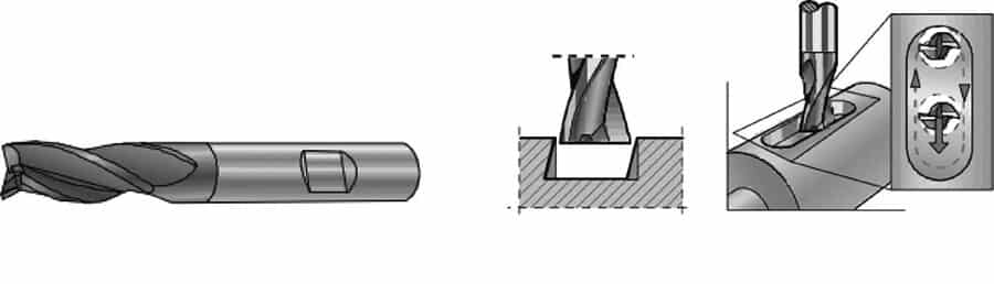
Keyway milling refers to the processing of creating keyways using a milling machine. The keyway milling cutter is a type of CNC milling tool that is mainly used for milling keyways and closed depressions.
To counteract the influence of radial cutting force, the keyway milling cutter is designed with two symmetrical cutting edges. During the milling process, the cutting forces on these edges create a force couple that cancels out the radial forces. The keyway milling cutter features cutting edges on both the cylindrical part and the end face. The cutting edge on the end face passes through the center of the tool, allowing for axial milling. It also possesses plunge drilling capabilities and can directly mill closed depressions.
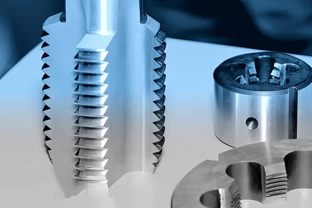
How to Select The Right Keyway Milling Cutter?
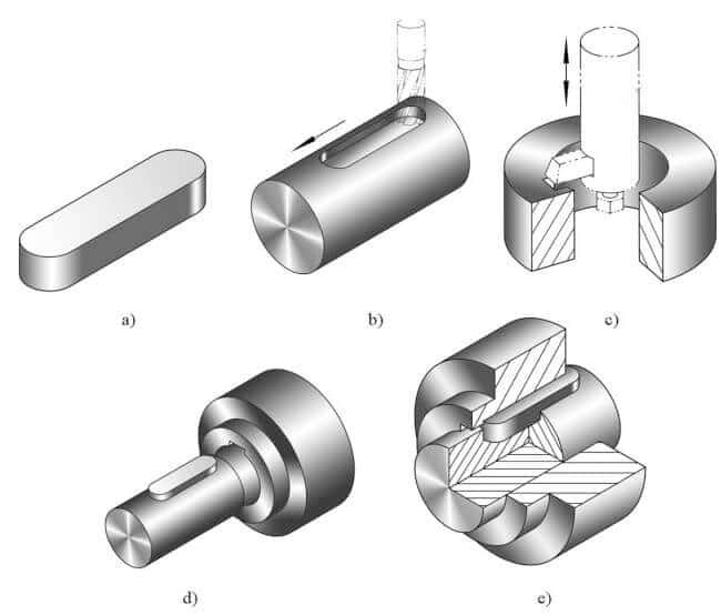
The keyway can be categorized into three types: open, semi-open, and closed. Typically, an open keyway is milled using a disc milling cutter, while a closed keyway is often machined using an end milling cutter or a specific keyway milling cutter. When employing an end mill, a hole with the same diameter as the milling cutter should be drilled at one end of the groove bottom, and its depth should match the depth of the groove.
The selection of milling cutting tools is of great significance for determining the precision, surface roughness, and productivity of the keyway during the milling process. Here are some milling tools recommended for different types of keyways:
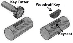
1. Shaft keyways for woodruff keys – Woodruff keyslot milling cutters
Milling a woodruff keyslot is a straightforward process, as it involves using a cutter that matches the diameter and thickness of the key. Position the milling cutter over the desired location for the keyway, and then move the workpiece up to the cutter until the desired depth of the keyseat is achieved. The workpiece can be secured in a vise, chuck, between centers, or clamped to the milling machine table. The size of the cutter determines whether it is held in an arbor or in a spring collet or drill chuck, which is mounted in the spindle of the milling machine.
2. Square-end keyways – Plain milling cutter or side milling cutter
Ensure that the workpiece is securely mounted and that the cutter is centered. Raise the workpiece until the milling cutter teeth make contact with it. Lock the graduated dial on the vertical feed and move the workpiece longitudinally to allow the cutter to clear it. Use the vertical hand feed screw to raise the workpiece until the cutter achieves the desired depth of cut. Once this adjustment is made, lock the vertical adjustment control and proceed to make the cut by feeding the table longitudinally.
3. Round-end keyways – End milling cutters
To mill rounded keyways, use an end milling cutter with the appropriate diameter. Similar to square-ended machine key keyways, make sure the workpiece is properly mounted and the cutter is centered in relation to the shaft. Position the shaft or cutter in a way that allows the end of the cutter to tear a thin piece of paper that is held between the workpiece and the cutter. Lock the graduated feed dial at this point and use it as a reference for setting the depth of the cutter. Clearly mark the ends of the keyway and move the workpiece back and forth, making multiple passes to minimize errors caused by the spring of the cutter.
Ways to Clamp and Calibrate the Workpiece
When working with a keyway milling machine, the workpiece is secured using a fixture, and the keyway milling cutter is used to gradually remove material layer by layer. It is important to ensure the stability and reliability of the workpiece during clamping. Additionally, it is crucial to maintain the central position of the clamped parts, ensuring that the centerline of the keyway aligns with the axis line. There are several common methods for clamping workpieces during keyway milling operations.
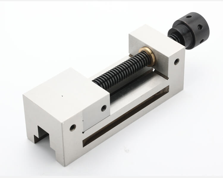
1. Use parallel-jaw vice
For milling keyways on small and medium-short shafts, using a machine vice for installation is appropriate. However, it is important to note that with changes in the diameter of the workpiece, the center of the part within the vice jaws may also shift. This can impact the symmetry and dimensions of the keyway. Despite this, using a machine vice is a stable, suitable, and simple method for single-piece production. It can also be used for mass production if the outer circle of the shaft has already been finished.
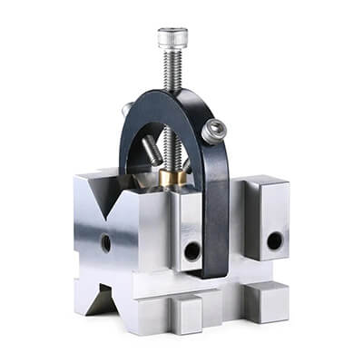
2. Use a v-shaped frame
For milling keyways on long and thick shafts, the V-shaped frame clamping method is appropriate. The V-frame provides excellent clamping stiffness, making it suitable for this application. It offers the advantage of convenient operation and easy alignment of the milling cutter. However, it’s important to note that the center of the workpiece is only positioned along the bisector of the V-shaped iron, and it can vary with the diameter of the shaft. Therefore, it is essential to align the center of the milling cutter with the bisector of the V-shaped iron to ensure the symmetry of the keyway.
3. Use T-slot
To machine long shafts with diameters ranging from 20 mm to 60 mm, an effective method is to place the shaft on the T-slot of the milling machine worktable and directly clamp it with a plate. This approach works well for this size range. However, it is not suitable for stepped shafts and large-diameter shafts.
4. Use index head
When installing a symmetric key and a multi-slot workpiece, it’s common to use a dividing head or fixture with an indexing device to ensure accurate distribution of the keyway positions on the shaft. To accomplish this, the workpiece is typically clamped using a three-jaw self-centering chuck and the back center of the dividing head. It is crucial that the axis of the workpiece aligns with the axis line between the three-jaw self-centering chuck and the center. Importantly, the position of the workpiece axis remains consistent regardless of changes in diameter. As a result, the symmetry of the keyway on the shaft will not be affected by variations in the workpiece diameter.
How to Align Milling Cutters?
As mentioned before, there are several ways to position the shaft when milling keyways. It can be supported in a vise or chuck, mounted between centers, or clamped to the milling machine table. The crucial aspect is ensuring that the cutter is centrally aligned with the axis of the workpiece. To achieve this alignment, one of the following methods can be employed:
To align the woodruff keyslot milling cutter properly, position the shaft in such a way that the side of the cutter is tangential to the circumference of the shaft. This can be accomplished by moving the shaft transversely until the workpiece touches the side teeth of the cutter. Once this contact is established, lock the graduated dial on the cross feed and lower the milling machine table. To finalize the alignment, use the cross-feed graduated dial as a guide and move the shaft transversely to a distance equivalent to the radius of the shaft plus half the width of the cutter.
When aligning end mills centrally, start by bringing the workpiece into contact with the periphery of the cutter. Then, follow the same procedure as described in the previous paragraph.
Milling of Keyways
Layered Milling
Layered milling involves cutting the keyway in layers, with each operation having a depth of only 0.5-1 mm. The milling process continues by moving the cutter back and forth with a larger feed rate until the desired depth is achieved.
One advantage of this method is that if the milling cutter becomes dull, it can be easily sharpened by grinding the end face without affecting the cutter diameter. However, when performing this technique on a regular milling machine, the operation flexibility is limited, and the production efficiency is lower compared to conventional cutting methods.
Expand Milling
To ensure proper milling of the keyway, start by grinding the selected milling cutter. Reduce its outer diameter by 0.3-0.5 mm while maintaining good cylindricity. When milling, leave a 0.5 mm allowance at both ends of the keyway. Move the cutter back and forth during the milling process.
Afterward, measure the groove width to determine the necessary width allowance. Proceed by using a milling cutter that matches the size of the keyway to mill both sides of the keyway to the desired size. Simultaneously, ensure that the keyway is milled to the required length.
Throughout the milling process, it’s vital to maintain the roundness of the circular arc at both ends of the keyway. It’s important to note, however, that this milling method can potentially result in a slope on the side of the groove.
Other Options for Keyway Cutting and Broaching
Keyways can be frequently found in various components such as gears, impellers, couplings, pump sleeves, stub shafts, and other parts that require internal keyways or slots for connections. While milling machines are commonly used for cutting keyways, there are also alternative methods available, such as EDM, shaping machines, or key seating machines.
1. Keyseating (for large & specialty keyways)
Keyway cutting using a keyseater machine, also known as an internal keyway slotting machine, involves the removal of material through a series of tooth cutting strokes. In some keyseaters, a single tooth cutter is used, while others utilize a multiple tooth cutter to achieve high cutting speeds similar to broaching.
The keyseater operates by gradually advancing the cutter outward with each subsequent cut. This incremental movement allows for the removal of a small amount of material in each stroke. The process continues until the cut reaches the required depth specified in the coupling hub print drawing.
Keyseating offers notable advantages, especially when dealing with large or specialty keyways. Custom-sized tooth cutters can be easily obtained and modified to meet unique specifications in an onsite tool room. However, it’s important to consider that keyseating may require a longer cycle time compared to traditional broaching, depending on the type of machine and cutting tool used.
2. Keyway Broaching (for speed)
Keyway cutting with a broaching machine follows a similar principle to keyseating. However, broaching machines commonly feature cutters with multiple teeth. As the cutter on the broaching machine is pushed through a hub, it removes progressively more material with each tooth as it advances. The presence of multiple teeth enables faster removal of material. Typically, keyway broaching can achieve the desired result in 1-3 strokes.
Like other cutting tools, broach cutting teeth need to be sharpened when they become dull. Additionally, broaching machines can be aligned horizontally or vertically to either push or pull the broach through the part.
One drawback of broaching is the initial cost of the broaches, which can be quite high, sometimes reaching tens of thousands of dollars. Regular maintenance is also necessary for broaches. Another consideration is the time factor. If a custom broach is not readily available, manufacturing one can take several weeks to months.
3. Wire EDM (for small, specialty runs)
Keyway cutting with wire EDM (Electric Discharge Machining) is typically employed for precision cutting or when specific cutting options are required, particularly for small quantity runs. Tool and die builders utilize wire EDM to remove material using a method that can be described as “evaporation” or “shock”. In this technique, a spooling copper wire is positioned close to the target to cut it using electrical sparks, without direct contact with the component.
If speed is a crucial factor, wire EDM may not be the most suitable choice for keyway cutting. A standard wire EDM machine typically operates at a rate of 12 square inches per hour. For instance, if the part is 6″ thick, the wire EDM machine will cut at a depth of 2″ per hour. However, one advantageous aspect of wire EDM is that these machines can run without the need for an active operator. Consequently, wire EDM is particularly suitable for certain applications such as prototype parts, rush orders, and one-off requests.
4. Shaping (for blind keyways)
Shaping is a viable option for cutting blind keyways, which refers to keyways that do not extend through the entire length of the part. Unlike broaching and wire EDM, which are not well-suited for blind keyways, shaping can effectively handle this type of cutting requirement.
Similar to some keyseaters, shaping involves the use of a single-tooth cutting tool. However, unlike keyseaters, shapers do not guide the tool down through the cut on a fixed post. Consequently, shaper cuts may not achieve the same level of accuracy as keyseater cuts as a result of unguided deflection. This highlights the importance of conducting proper tolerance inspections to ensure accuracy.
To cut blind keyways using a shaper, users must pre-cut a “relief” at the end of the keyway to be cut. This relief allows the metal chips to break and be cleared effectively. The relief can be created by cutting an internal groove on the inside diameter for hubs or by pre-drilling a hole, depending on the specific requirements of the keyway.
Conclusion
There are various types of keyways, and it’s essential to analyze the specific keyway types in order to determine the appropriate milling cutter and processing method. By using a flexible approach, you can enhance the efficiency of the processing and production.
If you are ready to embark on keyway cutting or seeking ways to reduce cycle time and manufacturing costs in your current keyway cutting process, Runsom Precision is here to assist you. We have specialized in CNC machining services with over a decade of experience and advanced technologies. Whether your project requires custom parts with multiple keyways or complex designs, we’re ready to offer you a comprehensive solution suitable for your application. Get an instant quote to start your project today!
Other Articles You May Be Interested in: