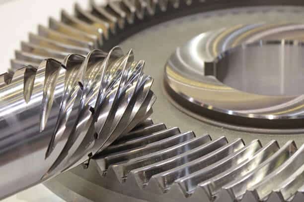

Gears have persisted for centuries, making them one of the oldest yet still pertinent mechanical elements today.
Various methods, including casting, forging, extrusion, powder metallurgy, blanking, and gear milling, can be employed to craft gears. There is no single process for gear manufacturing as they require different processes depending on the type and application. However, the machining process holds significant importance in attaining the ultimate gear size, shape, and surface finish.
This guide will explore gear manufacturing, covering common processes, post-processing operations, and materials.
What is Gear Manufacturing?
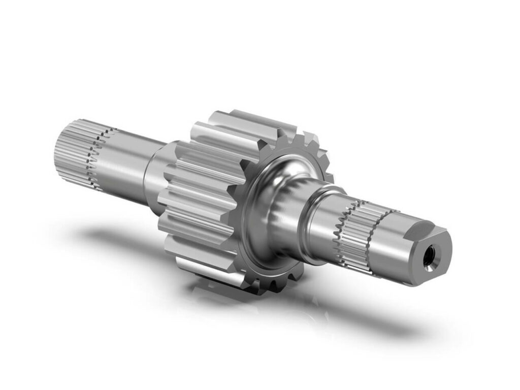
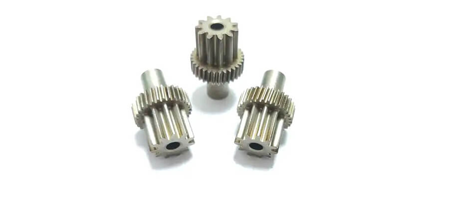
The process of gear manufacturing involves the precise production and shaping of gears, which are essential components used in machinery to transmit torque. Gears, known for their rotational motion, have teeth that interlock with those of another toothed mechanism, allowing for the smooth transfer of mechanical power.
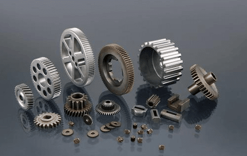
The creation of gears is realized through various methods, including machining, powder metallurgy, casting, and stamping. Gear milling, broaching, and hobbling are among the most precise and popular techniques used to achieve intricate and well-defined gear profiles. These methods ensure the precise crafting of gears necessary for various applications in machinery.
Various materials, such as metals, plastics, and even wood, are utilized in gear construction. Technological progress has enabled the formation of metal and plastic gears through die casting or injection molding, offering alternative manufacturing methods. This allows manufacturers to explore options beyond traditional gear production. Nevertheless, it is essential to recognize that some situations require post-processing operations to enhance the quality of the final gear product.
Typical Gear Manufacturing Processes
Gear fabrication methods have been typically classified into three main categories: generation, forming, and form cutting.
- Gear forming creates gears without using cutting tools (i.e. casting, forging, powder metallurgy, 3D printing)
- Gear form cutting involves tools that are used to create the gear profile (i.e. gear milling, broaching, and EDM)
- Gear generation uses cutting tools in the shape of the desired gear profile to create the gear (i.e. gear shaping and gear hobbing)
Gear Forming
Casting
Casting is a shaping process in which molten metal is poured into a mold cavity to create shapes. It is a relatively straightforward process primarily used to produce blanks or cylinders for gears, while the teeth are typically crafted through machining.
Yet, there is a specific area where casting reigns as the preferred manufacturing method in the industry: the production of very large gears. Machining methods and other gear forming techniques are less practical for large diameters. Typically, larger gears are predominantly of the spur gear type, further establishing casting as an excellent option due to its relative simplicity.
Shell casting, die casting, sand casting, and permanent mold casting are the most prevalent types of casting methods used for gear production.
Forging
This process offers the flexibility to produce both blanks and finished gears based on specific requirements. Forging is particularly suitable for relatively uncomplicated gears.
In theory, forging is an excellent gear manufacturing method for heavy-duty applications due to a simple rationale. The heat treatment involved in forging leads to gears with improved fatigue properties. However, the substantial force required for forging restricts the size and thinness of the gears produced.
Typically, forging is effective for gears ranging from 6 to 10 feet in diameter. Depending on the forging type, such as precision forging, machining may or may not be necessary for the final gear product.
Additive Manufacturing
Additive Manufacturing, commonly referred to as 3D printing, operates by building a three-dimensional object layer by layer, based on a CAD 3D model. This approach allows additive machines to produce intricate designs, incorporating lattice structures designed to reduce mass, a feat not easily achievable through traditional methods. The creation of such geometries often involves the use of 3D topology optimization and generative computer design.
Additive manufacturing processes can be utilized to fabricate conventional and non-circular gears. Furthermore, high-quality 3D printers are now reasonably priced and readily accessible.
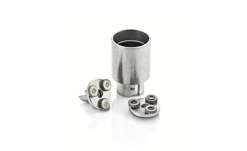
Powder Metallurgy
Powder metallurgy serves as a high-precision forming method that presents a cost-effective alternative to traditional, machine-finished steel and cast iron gears. However, it is not suitable for larger gear sizes and instead excels in producing small, high-quality spur, bevel, and spiral gears.
The porosity of the resulting material in larger gears leads to reduced fatigue and impact resistance, limiting their load-bearing capacity. Nonetheless, employing a sintering process can enhance their mechanical properties.
This method proves advantageous for gear designs incorporating features like holes, depressions, and varying surface levels or projections. Despite these benefits, the initial setup cost for powder metallurgy is considerably high, rendering it impractical for low-volume production.
Blanking
Blanking, similar to extrusion, shares many similarities but is constrained in its 3-dimensional capabilities. This method of gear formation employs sheet metal and multiple dies to achieve the desired shape. Various types of gears can be produced using the blanking process, with spur gears delivering optimal results.
In present times, the blanking process finds application in gear production across multiple industries, particularly for lightweight uses. These include office equipment, hydraulics, small medical devices, and other applications with relatively low load demands.
Gear Form Cutting
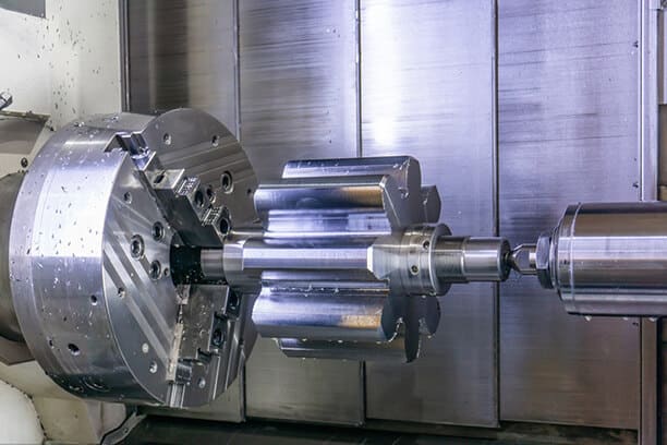
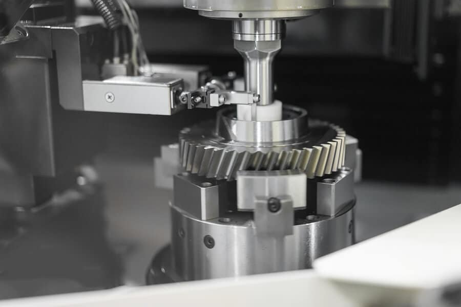
Milling
Gear milling involves the use of a form-cutting tool on a milling machine to carve gear teeth from a gear blank. This fundamental machining process relies on the movement between a rotating, multi-edge cutter and a workpiece to shape individual gear teeth.
While the milling form cutting method is somewhat restricted in its application, it excels in producing intricate gear geometries and can execute custom cuts without requiring special tooling.
CNC milling is commonly employed to fabricate helical and spur gear wheels for diverse industries, such as automobile transmissions, as well as hob cutters.
Broaching
Broaching stands out as one of the swiftest techniques for gear form cutting. It employs a multi-tooth cutting tool known as a broach, with each tooth being typically taller than the previous one. This incremental height variation facilitates the creation of smaller, easier cuts, quickly yielding the desired shape without sacrificing precision.
While this gear production method is commonly associated with internal gears, it also lends itself to creating external teeth. To accomplish this, a specialized tool for “pot broaching” is utilized, ensuring replication of the same level of precision and efficiency.
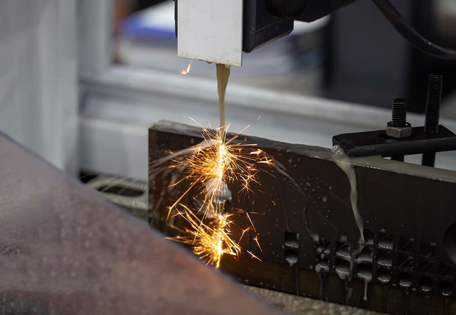
Electrical Discharge Machining (EDM)
EDM represents an electromechanical manufacturing technique in which material is eradicated from a workpiece by evoking a sequence of current discharges between two electrodes divided by a dielectric bath liquid. Instead of cutting, the spark serves as a “cutting tool” that essentially erodes the material.
EDM excels in cutting intricate geometries of all sizes, including as a gear cutting process. However, the method does have its drawbacks. The absence of precise control and programming may result in damaged part surfaces, particularly challenging for CNC programs to execute curved teeth profiles. Nevertheless, the application of high-quality and user-friendly 3D modeling and CAM software, such as Feature CAM, Autodesk Fusion, Master CAM, and others, can facilitate the smooth motion necessary for cutting curved teeth.
In recent years, EDM machines have undergone enhancements, diminishing issues with surface finishes and elevating cutting precision and resulting material properties (microstructure, mechanical properties, etc). This process can achieve tight tolerances as minute as thousandths of an inch and craft both diminutive (with a fraction of an inch in diameter) and substantial gears (with a diameter exceeding 20 inches). EDM is employed for delicate applications in watches and clocks as well as for cutting robust gears, including those used in race cars.
Gear Generation
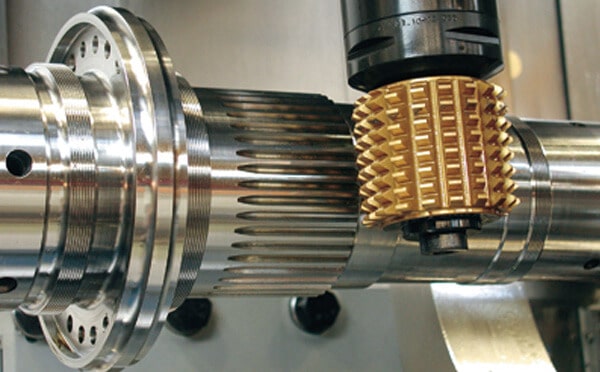
Gear Hobbing
The process of gear hobbing involves the use of a conical cutting device known as a hob, with both the hob and the workpiece rotating as the hob revolves around the gear blank.
Primarily, spur gears are produced using this method, although a range of other gears, including cycloid gears, helical gears, worm gears, ratchets, and sprockets, are all manufactured through hobbing. The quality of the hob is of utmost importance, particularly when cutting intricate geometries.
Gear hobbing is generally unsuitable for internal gears. Similar to gear shaping, hobbing offers setup advantages but is limited to external cuts, as the hob carves the exterior of the gear blanks.
Gear Shaping
The gear shaping process involves a cutter with a profile matching the desired tooth geometry. This cutting tool utilizes linear motion to remove material from the gear blank, comprising a cutting and return stroke. The pitch of the gear shaping tool aligns with the pitch required for the gear tooth, accommodating gears with varying tooth quantities.
Gear shaping proves to be a viable solution for medium-sized production runs, offering speed, design, and setup advantages for mass production and facilitating the creation of most gear types, with the exception of worm gears and internal gears. However, the drawback of gear shaping lies in the cutting arm’s limited rigidity, resulting in reduced accuracy.
Sunderland Method
Among the primary gear manufacturing techniques, rack-type cutters play a prominent role. The process of gear rack cutting, also referred to as the Sunderland Method or the Sunderland System, involves a gear machine equipped with a rack cutter featuring rake and clearance angles to shape teeth profiles on a gear blank. This method relies on the specific relative motion between the workpiece and the cutter during machining, similar to a rack and pinion.
The Sunderland Method excels in producing uniform teeth shapes, and gears cut by the same cutter are theoretically capable of meshing correctly with each other. As a result, gear designs requiring high precision, including double helix gears, can be effectively produced using this method. Furthermore, the Sunderland Method proves to be versatile and cost-effective, particularly for medium to high-volume production runs.
Post-Processing for Gear Manufacturing
Upon completion of the gear manufacturing processes detailed above, the surface finish and dimensional accuracy of the gears may not meet the specific requirements for certain applications. Consequently, a series of finishing operations becomes necessary. These post-processing activities encompass a range of treatments, including heat treatment to enhance fatigue characteristics, as well as dimensional correction and surface finishing.
Here are the five most common surface finishing processes frequently employed in gear production.
- Grinding: This well-known surface finishing process effectively provides a smooth finish across the surface, as the name implies. It can be executed intermittently or continuously without affecting the results.
- Lapping: Suited for delicate gears requiring utmost precision, lapping employs small abrasive particles to meticulously smooth a surface at low or medium speeds.
- Honing: Another widely used process, honing polishes the surface, imparting a smooth texture while also correcting minor errors in tooth geometry.
- Shaving: Involving the removal of exceedingly thin layers from the surface to attain a smooth profile, shaving is a relatively costly process and is infrequently utilized in gear production.
- Burnishing: This technique involves utilizing compression to refine the surface, essentially smoothing it out.
Materials Available for Gear Manufacturing
For reliable performance and an extended lifespan, a gear must possess specific characteristics, including:
- Low coefficient of friction
- Excellent manufacturability
- High tensile strength to endure static loads
- High endurance to withstand load variations
Numerous materials are employed in the production of gears to impart these critical properties. Below is an outline of each material and its distinctive strengths.
Cast Iron
Cast iron can endure repeated and sustained wear, rendering it well-suited for precision gear manufacturing. The casting process enables the production of intricate gear shapes with ease. Cast iron gears are frequently utilized in applications where smooth action is not a primary concern.
Steel
Gears made from steel alloys boast high strength as they are commonly subjected to heat treatment to improve toughness and hardness, particularly in the teeth. Notably, carbon steel is utilized in the production of helical, spur, bevel, worm, and gear racks.
Brass
A combination of copper and zinc, brass is an alloy that allows manufacturers to adjust the zinc content. Brass with low zinc levels offers greater ductility compared to other materials, and its copper base renders the metal antimicrobial and easy to machine. Typically, brass gears are employed in low-load applications such as spur gears or gear racks.
Bronze
Apart from brass, other copper alloys also contain aluminum bronze and phosphor bronze alloys. These nonmagnetic gears are most suitable for use in corrosive environments.
Combining copper, tin, and phosphorus, phosphor bronze offers enhanced strength and corrosion resistance due to the presence of tin, while the addition of phosphorus improves its stiffness and wear resistance. This makes phosphor bronze gears well-suited for high-friction environments, particularly in worm gears, as the material effectively withstands the friction caused by the wheel and minimizes the effects of lubrication.
Comprised of copper, aluminum, nickel, iron, and manganese, aluminum bronze exhibits exceptional resilience against wear and corrosion, making it a preferred choice for use in highly corrosive settings exposed to saltwater, oxidation, and organic acids. Moreover, its ability to thrive in high-load environments renders it suitable for applications involving worm wheels and screw gears.
Aluminum Alloys
In settings that demand gears with a high strength-to-weight ratio, aluminum alloys serve as a viable substitute for iron alloys. Additionally, gears crafted from aluminum alloys benefit from a protective surface finish called passivation, safeguarding them against corrosion and oxidation.
The prevalent aluminum alloys utilized in gear manufacturing comprise 2024, 6061, and 7075. Regardless of the grade, aluminum gears are most suitable for applications with low to moderate temperatures, as they start to degrade at approximately 400 °F.
Powdered Metals
These metals consist of various combinations of metal materials, including iron-nickel steel, pre-alloyed steel, and customized blends. Additionally, their porosity contributes to quieter gear operation, and they can be made self-lubricating through vacuum impregnation with different oils.
The process involves three key steps:
- Developing the optimal combination that aligns with specifications for durability, precision, and dependability
- Compacting the mixture under controlled pressure to meet exact requirements
- Heating or sintering the blend to yield a permanent form
Powder metallurgy is capable of producing bevel, spiral bevel, spur, helical, pinion, and combination gears.
Thermoplastics
In precision manufacturing, lightweight gears rely significantly on thermoplastics. These gears can be produced similarly to metallic gears, with injection molding often being the preferred method. Acetal is a popular choice among manufacturers due to its stability across broad temperature ranges, low coefficient of friction, and resistance to creep.
Custom Gear Manufacturing Solutions Provider – Runsom Precision
Operating within the highly specialized field of gear manufacturing demands high precision and accuracy. Due to their crucial role in mechanical systems, even the most minor manufacturing imperfections can cause severe consequences. Thus, it is recommended to carefully choose your service provider.
When it comes to precision gear machining, Runsom Precision is ready to help. We specialize in fabricating custom, precision gears using an array of materials through our CNC machining services. With our incredible manufacturing capabilities, gear and mechanical part making becomes faster, more streamlined, and notably more efficient. Reach out to our experts today for an instant quote and start your next project.
Explore more about our Custom Gear Manufacturing capabilities.
Other Articles You May Be Interested in: