
When it comes to precision CNC machining where every detail and dimensional tolerance are crucial, two important concepts play a significant role: straightness and flatness.
Straightness and flatness help define the shape and form of a feature on a part, and understanding each one is essential for achieving meticulous accuracy. These two terms are often used interchangeably, while in Geometric Dimensioning and Tolerancing (GD&T), they have distinct definitions and purposes.
Here, we will outline the definitions of straightness and flatness in GD&T and their difference, as well as discuss measurement methods.
Straightness in GD&T
Straightness tolerance, a 2-dimensional GD&T callout, is used to control the straightness of part features. No axis can ever be perfectly straight. The straightness tolerance defines the total allowable variation of a single actual straight line, ensuring that it is sufficiently straight for the intended application.

To visualize the straightness tolerance, imagine setting an imaginary boundary as below. This boundary represents the tolerance zone and its size is defined by a value in the tolerance frame, typically expressed in hundred-thousandths of an inch. Within this tolerance boundary, the line formed by the intersection of the top surface of the plate and the section plane can take on any shape.
In GD&T, straightness serves two distinct purposes: controlling the straightness of a surface and the straightness of an axis. The normal form surface straightness is a tolerance used to regulate the form of a line on the surface of a feature. On the other hand, axis straightness is a tolerance that governs the amount of curvature allowed in the axis of the machined part.
Additionally, it’s important to note that the feature control frame differs for each of these functions. Now, let’s explore and understand each of these functions in more detail.
Surface straightness
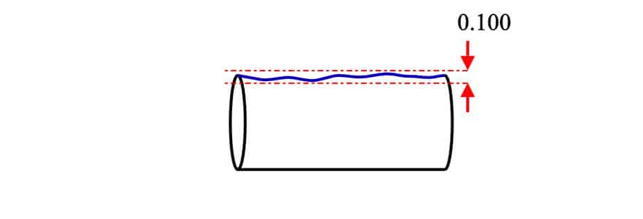
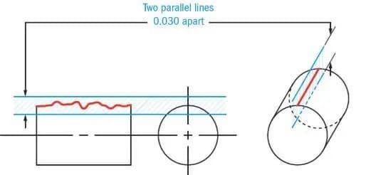
When the straightness callout is applied to specify surface straightness, the tolerance zone encompasses a total width above and below the ideal surface position, controlling any deviations. Surface straightness serves to regulate the form of a line on the surface and can be applied in two different scenarios:
- The first involves a flat surface, like the face of a cube.
- The second pertains to a cylindrical surface in the axial direction.
In both cases, the tolerance zone takes the form of a 2D plane. This plane is visualized as two parallel lines (also parallel to the surface) that are positioned above and below the surface respectively.
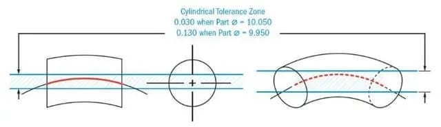
Axis straightness
The straightness callout also has the function of controlling the straightness of an axis. It is crucial to control the amount of linear deviation in the axis to ensure a smooth assembly. By using the straightness callout, the deviation of the derived median line can be kept within acceptable limits.
In this case, the tolerance zone is not applied to the surface but to the axis of the part. Additionally, instead of being positioned above and below the axis, the tolerance zone takes the form of a cylindrical area surrounding the center axis.
Feature Control Frame (FCF) of Straightness

The feature control frame offers all the essential information regarding the tolerance.
Surface straightness FCF
When applying GD&T to control surface straightness, the geometric characteristic block includes the symbol for straightness, which is represented by a short horizontal line resembling a hyphen.
The second block contains information about the tolerance zone type, tolerance value, and any material modifiers (such as maximum material condition) if applicable. Since the tolerance zone type is a total width zone, no additional symbols are required, as this is the default zone type.
The straightness callout, like other form controls, does not require a datum. The leader arrow is used solely to indicate the surface that needs to be controlled.
Axis straightness FCF
In the case of axis straightness, the feature control frame is mostly similar, with the addition of a symbol representing the type of tolerance zone. Since this zone is cylindrical, the second block includes the diameter symbol to indicate this.
Another difference is that, for axis straightness, the leader arrow no longer marks the surface but instead points to the part’s diametric size dimension.
When the arrow is directed towards a specific size dimension, it indicates that the FCF is controlling the center plane or the axis of the feature. Therefore, pointing to the part’s diametric dimension signifies that the straightness callout is controlling the axis of the part.
Flatness in GD&T
Flatness is a geometric characteristic in GD&T that regulates the form of a surface. Its purpose is to define the acceptable variation in the shape of a surface, ensuring that it remains within a specified tolerance zone. This tolerance zone is determined by two parallel planes that are equidistant from the ideal surface. Any deviations of the surface within this tolerance zone are allowable.
Flatness is commonly employed to regulate the planar attributes of surfaces, specifically the top or bottom surfaces of a part. Its primary purpose is to ensure that a surface remains free from twisting, warping, or any other types of distortion that could potentially impact the functionality or assembly of the part. The tolerance value for flatness is typically expressed in units of length, such as millimeters or inches, and represents the maximum permissible variation in the shape of the surface.
Difference Between Straightness and Flatness
Although both straightness and flatness address deviations from an ideal form, there are significant differences between the two:
- Dimensional focus: Straightness focuses on controlling the form of a line or feature in 2D, while flatness controls the form of a surface in 3D.
- Tolerance zone shape: Straightness establishes a cylindrical tolerance zone around the ideal line, while flatness establishes a parallel planar tolerance zone around the ideal surface.
- Feature types: Straightness is applicable to axes, lines, centerlines, and edges, whereas flatness is available for planar surfaces.
- Geometric application: Straightness is generally used to align features or control linear motion, whereas flatness is used to ensure planarity or proper contact between surfaces.
- In terms of surface shapes, flatness is inversely proportional to bumpiness, and for linear shapes, straightness is inversely proportional to curviness.
How to Measure Straightness and Flatness
Measuring Straightness
When evaluating straightness, you are examining the degree to which a target aligns with a straight line and identifying any warping or curvature present in elongated objects.
Using a Height Gauge
To measure straightness, ensure that the target is securely positioned with equal height on both the left and right sides. Use small jacks if necessary to prevent any tilting. Then, move either the target or the height gauge in a straight line to measure the straightness.
The straightness is determined by calculating the difference between the maximum and minimum height values (ΔH).
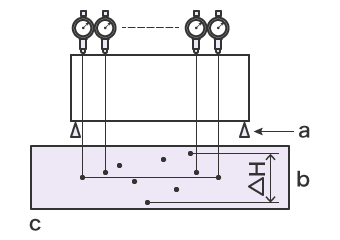
a: Micro jack
b: △H = straightness
c: Height (Hn) graph
Generally, height gauges have lower precision compared to coordinate measuring machines (CMM). Moreover, the measured values can be influenced by the force applied while placing the height gauge on the target, leading to unstable measurement results. In cases where the target cannot be leveled, moving the height gauge becomes challenging, making the measurement process difficult.
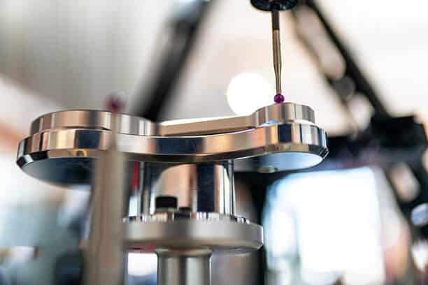
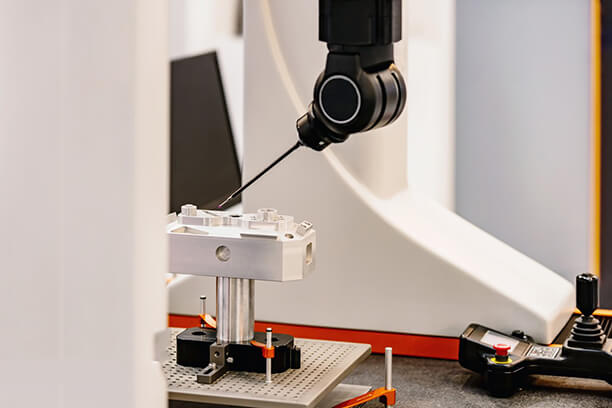
Using a Coordinate Measuring Machine (CMM)
Straightness can be measured using a CMM by lightly placing the stylus on the target. This method eliminates errors caused by measurement pressure and allows for stable measurement results.
Furthermore, the stylus can be positioned on the target from various angles, enabling accurate measurement of targets that cannot be leveled or measured using a height gauge.
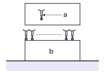
a: Stylus
b: Target
Measuring Flatness
The approach for verifying if the final measurements adhere to the specified flatness tolerance varies depending on the surface being inspected. Therefore, we will discuss each instance individually.
Single planar surfaces
To measure flatness, you will need a surface plate and either a height gauge, a probe, or another suitable surface. It is important to note that you cannot measure flatness simply by placing the part on a surface plate or slab and using a height gauge, as this would be measuring parallelism with respect to the bottom surface.
1. Using a height gauge
To gauge the flatness of a surface using a height gauge, it’s essential to maintain the reference feature in a parallel position. The height gauge should be moved across the entire surface, ensuring that it covers every area. By measuring the maximum positive and negative heights recorded on the gauge, we can calculate the total variance. To approve the part, this variance should not exceed the specified flatness tolerance value.
2. Using a surface plate
Machinists employ a surface plate to assess the flatness of a part. The part is positioned face down on the surface plate, and a height gauge is used to make contact with the designated surface through a hole in the plate.
Subsequently, the height gauge and the part are maneuvered in a manner that encompasses the complete length and width of the surface. This enables the calculation of the flatness variance of the actual surface.
Feature of size (Flatness at MMC)
To evaluate flatness at Maximum Material Condition (MMC), we are essentially measuring the flatness of the resulting median plane. When examining flatness in relation to a feature of size, there are two approaches available:
1. Using a functional gauge
In this approach, we utilize two height gauges positioned at opposite ends of the feature of size. Let’s consider a flat plate where the feature of size, controlled by the flatness callout, is its width.
We place a height gauge on the top and bottom surfaces, aligning them with each other. These height gauges measure the local thickness. They are then moved across the entire surface to ensure that the entire surface falls within the size tolerance.
The second method involves using a gauge that has a cavity specifically designed to fit the plate at the boundary of the virtual condition. The virtual condition boundary represents the maximum allowable tolerance when we consider the combination of the geometric tolerance and MMC. To approve the part, the plate must fit within this gauge.
2. Using a CMM
A Coordinate Measuring Machine (CMM) is capable of performing various types of measurements. However, measuring this particular callout requires some additional preparations.
Using the same plate mentioned earlier, with the same feature of size (FOS) under control, the plate needs to be positioned in a way that allows the probe to reach both surfaces. We proceed by marking points on the surface and measuring the local thickness at these points. If these thicknesses fall within the specified size limits, we then calculate the midpoint between these opposing points and connect them to form the derived median plane.
To determine the flatness tolerance, we subtract the maximum local thickness of the plate. If the flatness variance of the derived median plane is less than the specified flatness tolerance, then the part is considered to be within specification.
FAQs
Conclusion
In GD&T, straightness and flatness are two separate characteristics utilized to control the form of lines/edges and surfaces, respectively. Straightness ensures that a line or feature remains within a designated tolerance zone, while flatness ensures the planar shape of a surface. It’s vital to understand the distinction between these two GD&T symbols for precise communication of design and manufacturing specifications. By applying the proper straightness or flatness tolerance, engineers and manufacturers can achieve the desired fit, functionality, and assembly of parts, ultimately improving the overall quality of the product.
Get Custom Precision CNC Machined Parts with Tight Tolerance from Runsom Precision
If you are looking for CNC machined parts with precise tolerances and high quality, Runsom Precision is a reliable option. We specialize in precision CNC machining services to produce custom parts using various materials. Our team of experienced professionals utilizes advanced equipment and testing instruments, including the coordinate measuring machine (CMM), to ensure that all parts meet the required tolerances and standards. Simply upload your files and receive an instant quote today!
Other Articles You May Be Interested in: