
Dimensional tolerance is of great importance in precision CNC machining as it directly affects the accuracy and functionality of machined parts. ISO 2768 is a critical standard that clarifies the tolerance value of a specific CNC machined part and ensures its consistency in dimensional tolerances.
For machined parts, the ISO 2768 standard serves as a useful tool for manufacturers to preserve uniformity in dimensions. This standard ensures that machined parts possess compatibility and interchangeability. By utilizing the ISO 2768 standard, machinists and designers have the ability to determine the allowable level of deviation from the original specifications, allowing for a controlled margin of error. The tolerance limits provided by ISO 2768 establish a range of acceptable variation between nominal dimensions and other dimensional values as per the required criteria.
This article aims to review the details of ISO 2768, offering a comprehensive understanding of this tolerance standard and its importance for CNC machining processes. We also offer ISO 2768 tolerance charts for reference and PDFs available for download.
ISO 2768-1: Linear and Angular Dimensions
ISO 2768-1 is a standard that addresses general tolerances for linear and angular dimensions, specifically those without individual tolerance indications. This standard applies to various dimensions, including internal sizes, external sizes, step sizes, diameters, radii, outer radii, distances, and chamfer heights for broken edges. The primary purpose of ISO 2768-1 is to simplify drawing indications by providing general tolerances classified into four different tolerance classes:
- f – Fine tolerances
- m – Medium tolerances
- c – Coarse tolerances
- v – Very coarse tolerances
In accordance with the ISO 2768 standard, Table 1 displays the tolerance class designation or precision levels for linear dimensions.
Table 1 – Linear Dimensions
| Permissible deviations in mm for ranges in nominal lengths | Tolerance Class Designation (Description) | |||
| f (fine) | m (medium) | c (coarse) | v (very coarse) | |
| 0.5 up to 3 | ±0.05 | ±0.1 | ±0.2 | – |
| over 3 up to 6 | ±0.05 | ±0.1 | ±0.3 | ±0.5 |
| over 6 up to 30 | ±0.1 | ±0.2 | ±0.5 | ±1.0 |
| over 30 up to 120 | ±0.15 | ±0.3 | ±0.8 | ±1.5 |
| over 120 up to 400 | ±0.2 | ±0.5 | ±1.2 | ±2.5 |
| over 400 up to 1000 | ±0.3 | ±0.8 | ±2.0 | ±4.0 |
| over 1000 up to 2000 | ±0.5 | ±1.2 | ±3.0 | ±6.0 |
| over 2000 up to 4000 | – | ±2.0 | ±4.0 | ±8.0 |
The deviations shall be indicated alongside the corresponding nominal size(s) for nominal sizes below 0.5 mm.
Table 2 – External Radii and Chamfer Heights
Likewise, Table 2 illustrates the tolerances for external radii and chamfers.
| Permissible deviations in mm for ranges in nominal lengths | Tolerance Class Designation (Description) | |||
| f (fine) | m (medium) | c (coarse) | v (very coarse) | |
| 0.5 up to 3 | ±0.2 | ±0.2 | ±0.4 | ±0.4 |
| over 3 up to 6 | ±0.5 | ±0.5 | ±1.0 | ±1.0 |
| over 6 | ±1.0 | ±1.0 | ±2.0 | ±2.0 |
The deviations shall be indicated alongside the corresponding nominal size(s) for nominal sizes below 0.5 mm.
Table 3 – Angular Dimensions
Table 3 stands as the definition of the general tolerances for angles and angular dimensions. It is worth noting that the tolerance units in this table are measured in degrees and minutes, consistent with the nature of angular dimensions. However, in the subsequent section, we will explore the concept of “perpendicularity“, where it is interesting to observe that the units for perpendicularity, despite involving two surfaces in an angle, are actually expressed in length (mm).
| Permissible deviations in mm for ranges in nominal lengths | Tolerance Class Designation (Description) | |||
| f (fine) | m (medium) | c (coarse) | v (very coarse) | |
| up to 10 | ±1º | ±1º | ±1º30′ | ±3º |
| over 10 up to 50 | ±0º30′ | ±0º30′ | ±1º | ±2º |
| over 50 up to 120 | ±0º20′ | ±0º20′ | ±0º30′ | ±1º |
| over 120 up to 400 | ±0º10′ | ±0º10′ | ±0º15′ | ±0º30′ |
| over 400 | ±0º5′ | ±0º5′ | ±0º10′ | ±0º20′ |
ISO 2768-2: Geometrical Tolerances for Features
ISO 2768-2 defines the geometrical tolerances for features without individual tolerance indications. This standard establishes a general range for tolerances of flatness and straightness, cylindricity, and circularity. Within ISO 2768-2, there are three classes of tolerance denoted as H, K, and L.
Table 4 – General Tolerances on Straightness and Flatness
This table outlines the ranges for straightness and flatness. Straightness pertains to the degree of variation a surface can have within a specified line on that surface. Moreover, straightness can also be used to control the amount of bend or twist allowed for the axis of a part.
| Ranges of nominal lengths in mm | Tolerance Class | ||
| H | K | L | |
| up to 10 | 0.02 | 0.05 | 0.1 |
| above 10 to 30 | 0.05 | 0.1 | 0.2 |
| above 30 to 100 | 0.1 | 0.2 | 0.4 |
| above 100 to 300 | 0.2 | 0.4 | 0.8 |
| above 300 to 1000 | 0.3 | 0.6 | 1.2 |
| above 1000 to 3000 | 0.4 | 0.8 | 1.6 |
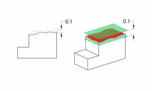
Table 5 – General Tolerances on Perpendicularity
Perpendicularity is a dimension-related attribute that is measured in units of distance, such as millimeters. The general tolerance standards for perpendicularity are consolidated and presented in Table 5.
| Ranges of nominal lengths in mm | Tolerance Class | ||
| H | K | L | |
| up to 100 | 0.2 | 0.4 | 0.6 |
| above 100 to 300 | 0.3 | 0.6 | 1.0 |
| above 300 to 1000 | 0.4 | 0.8 | 1.5 |
| above 1000 to 3000 | 0.5 | 1.0 | 2.0 |
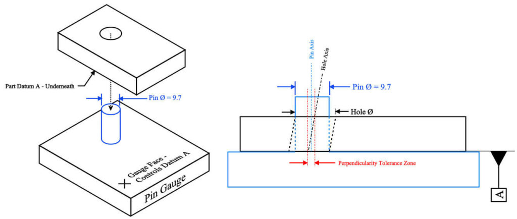
Table 6 – General Tolerances on Symmetry
Table 6 exhibits the general geometrical characteristics of Symmetry, registering permissible deviations for certain features that may possess uniformity across a plane.
| Ranges of nominal lengths in mm | Tolerance Class | ||
| H | K | L | |
| up to 100 | 0.5 | 0.6 | 0.6 |
| above 100 to 300 | 0.5 | 0.6 | 1.0 |
| above 300 to 1000 | 0.5 | 0.8 | 1.5 |
| above 1000 to 3000 | 0.5 | 1.0 | 2.0 |
Table 7 – General Tolerances on Circular Run-Out
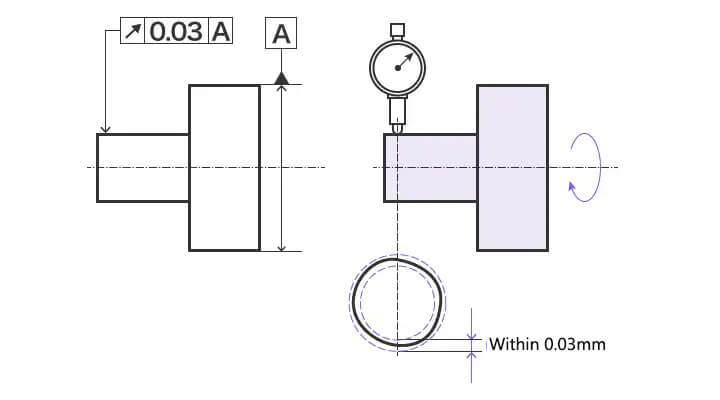
Table 7 corresponds to Run-out, which defines the overall variation that a surface may exhibit when the part is rotated around the axis of a datum.
| Ranges of nominal lengths in mm | Tolerance Class | ||
| H | K | L | |
| 0.1 | 0.2 | 0.5 | |
The general tolerance provided enables manufacturers to select the most suitable level of tolerance based on their specific requirements. For instance, if a part is intended for use in a project with stringent tolerance demands, opting for a narrow tolerance range would be prudent. Conversely, for high-volume production of parts intended for applications with lower tolerance requirements, a broader tolerance range would offer greater cost-effectiveness.
What Is ISO 2768?
Developed by the International Organization for Standardization (ISO), ISO 2768 is an internationally recognized standard that seeks to streamline mechanical tolerance specifications found in engineering drawings. Its purpose is to simplify the design and production processes, fostering better collaboration among various companies. This standard primarily applies to parts manufactured through machining or material removal methods. In cases where specific tolerance ranges are not explicitly indicated for a particular dimension, adherence to ISO 2768 is recommended.
ISO 2768 standards hold significance across various industries, spanning aerospace, automotive, electronics, and electrical sectors, to name a few. As an international manufacturing standard, ISO 2768 aids in establishing standard machining tolerances, mitigating inconsistencies while considering manufacturing costs.
What Are the Parts of ISO 2768?
ISO 2768 is comprised of two parts designed to streamline drawings by establishing precision levels as general guidelines:
- ISO 2768-1, titled “General tolerances for linear and angular dimensions,” defines precision levels categorized as f (fine), m (medium), c (coarse), and v (very coarse) – these correspond to the four tolerance classes in DIN ISO 2768.
- ISO 2768-2 concentrates on “Geometrical tolerances for features” and introduces different precision levels or tolerance classes: H, K, and L.
Adopting the ISO 2768 specification simplifies drawing by eliminating the need to specify tolerances for each dimension and feature individually. Instead, a drawing can be designated as ISO 2768-mK, indicating that it should adhere to the tolerance ranges specified for “medium” in Part 1 and tolerance class “K” in Part 2. ISO 2768-mK is commonly used in the manufacturing of sheet metal components, while ISO 2768-fH is often favored by manufacturers of machined components. More in-depth discussions on both ISO 2768 Part 1 and Part 2 can be found in the earlier sections.
The ISO 2768 standard consists of general rules, but it is important to note that there can be exceptions when specific dimensions on a part require tighter tolerances than those established by ISO 2768. These exceptions are normal and not uncommon in practice. Therefore, it is essential to always review the drawing title block to identify the general tolerance requirements, as well as any special part specifications or project-specific requirements that may deviate from the ISO 2768 standard.
What Industries and Manufacturing Involve Using ISO 2768?
ISO 2768 holds relevance across various industries and companies that engage in technical drawings and manufacturing processes. This includes:
- CNC Machining: ISO 2768 has an important impact on the CNC machining industry as it guarantees the production of consistently accurate machined parts. By strict adherence to the specified tolerances, it allows for the desired level of precision, functionality, and compatibility of components.
- Tooling and Mold-Making: ISO 2768 is utilized by companies involved in tooling and mold-making industries to establish tolerances for dies, molds, and tooling components. This standard ensures the accurate replication of shapes and dimensions for consistent production.
- Architecture and Construction: ISO 2768 can also be applied in the architecture and construction industries to ensure tolerances in building components and structural elements, promoting the proper alignment and assembly of various architectural elements.
- Manufacturing: ISO 2768 is applicable to a wide range of manufacturing sectors, including aerospace, automotive, electronics, consumer goods, and many more. Its implementation ensures the consistency and compatibility of parts and components produced by different manufacturers or suppliers within these industries.
- Industrial Design: ISO 2768 is pertinent to companies engaged in industrial design, offering guidelines for specifying tolerances in technical drawings to ensure the precise fit and optimal functionality of designed products.
What Are the Benefits of Using ISO 2768?
Incorporating ISO 2768 into technical drawings can be advantageous for organizations. Let’s explore some of the benefits of applying ISO 2768 standards in technical drawings:
- Interchangeability: ISO 2768 establishes standardized tolerance values, guaranteeing proper fit and compatibility of parts manufactured by different suppliers or companies. This enhances the interchangeability of components, facilitating assembly and maintenance processes.
- Design Consistency: ISO 2768 helps to foster design consistency by offering a set of predefined tolerances. This aids designers and engineers in maintaining uniformity in their drawings, ensuring clear and consistent specifications across various projects. Consequently, it helps prevent design errors.
- Quality Control: ISO 2768 assists organizations in maintaining quality control by outlining acceptable tolerances for dimensions. By referring to these standards, organizations can ensure that their products meet the required quality standards and fulfill customer expectations.
- Cost Reduction: Adhering to the tolerance guidelines provided by ISO 2768 allows organizations to minimize the need for expensive customization or adjustments. By utilizing standardized tolerances, the risk of errors, rework, and rejected parts is reduced, helping cost savings in production.
- International Compatibility: ISO standards, including ISO 2768, garner global recognition and acceptance. The use of ISO 2768 in technical drawings enhances international compatibility by providing a standardized reference for dimensions and tolerances across different countries and industries.
Certifications and Accreditations Similar to ISO 2768
Although ISO 2768 primarily focuses on general tolerances in technical drawings, there are various other certifications and accreditations related to different industries regarding quality management systems and product standards. Here are a few noteworthy examples:
- ISO 9001: Regarded as the most universally acknowledged standard for quality management systems, ISO 9001 establishes criteria for organizations to showcase their capability in consistently delivering products and services that meet customer requirements and regulatory standards. ISO 9001 exhibits overall principles and processes of quality management.
- ISO 14001: This standard specifically focuses on environmental management systems. It offers guidelines for organizations to establish, implement, maintain, and enhance their environmental management systems. By adhering to ISO 14001, organizations can effectively manage their environmental responsibilities, minimize their environmental impact, and contribute to sustainable practices.
- ISO/IEC 17025: This accreditation specifically targets testing and calibration laboratories. ISO/IEC 17025 establishes criteria to evaluate the impartiality, competence, and consistent operation of laboratories, thereby ensuring their ability to generate accurate and reliable test results. It encompasses aspects such as equipment calibration, quality control, and personnel competence.
- AS9100: This standard is tailored for the aerospace industry. AS9100 integrates ISO 9001 requirements while adding additional criteria specifically relevant to aerospace organizations. It concentrates on quality management systems within the aerospace sector, incorporating aspects like supply chain management, risk management, and configuration control.
- ISO/TS 16949: Specifically created for the automotive industry, ISO/TS 16949 details the requirements of the quality management system for organizations engaged in the design, development, production, installation, and servicing of automotive-related products. This standard places significant emphasis on process control and continuous improvement to ensure high-quality automotive products.
- ISO 13485: This standard is exclusive to the field of medical devices. ISO 13485 specifies the requirements for quality management systems in the design, development, production, and distribution of medical devices. It focuses on meeting regulatory and customer requirements associated with the safety and effectiveness of medical devices.
Conclusion
In this article, we have explored the ISO 2768 certification, providing an explanation and discussing its relevance in various industries. However, determining the appropriate level of tolerance for a part relies on its specific application and requirements. Factors such as materials, manufacturing processes, and cost considerations should also be taken into account when determining the optimal tolerance level for a part or product.
If your project requires the fabrication of a precise metal part with tight tolerances, CNC machining is an excellent option to consider. CNC machines are known for their high precision and can create parts with very tight tolerances. Typically, the tolerance range in CNC machining can vary from ±0.001″ to ±0.0001″.
Experts at Runsom Precision possess comprehensive knowledge of ISO 2768 tolerance and we are fully equipped to assist you in saving time and cost through our custom precision CNC machining services. Simply upload your files to receive an instant quote and get started on your project right now!
While ISO 2768 covers certain tolerances and geometric characteristics utilized in manufacturing, it is important to note that there exist additional standards within Geometric Dimensioning and Tolerancing (GD&T). For those who are interested in this topic, we recommend further readings on GD&T and exploring the ASME Y14.5 standard.
Download the PDF version:
FAQs
Other Articles You May Be Interested in: