
ASME Y14.5-2009 provides guidelines for 14 different types of geometric tolerances, each specifying a specific way to control various part features. To simplify understanding, these 14 types can be categorized into five main groups, which are form, profile, orientation, location, and runout.
Location controls are used to tightly control the position of a feature relative to a datum. Within the location category, there are three controls: concentricity, symmetry, and position.
Concentricity is a complex tolerance employed to guarantee precision and quality in manufacturing, including CNC machined parts. What exactly is concentricity in GD&T, how can it be measured, and what are its various aspects, applications, and distinctions from runout and position? Let’s explore the details of concentricity to address these questions.
What Is Concentricity in GD&T?
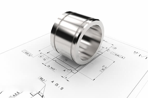
A high level of accuracy in the concentric design of mechanical parts is often necessary for satisfactory operation. For instance, tubes that withstand high pressures must be designed with a uniform wall thickness to prevent weak structural points. In GD&T(Geometric Dimensioning and Tolerance), concentricity is a 3D callout that ensures one or more part features are concentric around a datum axis.
However, in GD&T, the meaning of concentricity differs slightly from its literal definition commonly understood by engineers. The purpose of a concentricity callout is to ensure that the midpoint of two diametrically opposite points falls within a specified tolerance zone. Although the circular feature may have surface variations such as notches or dips, the mass distribution around the central axis should remain uniform.
This balanced mass distribution is crucial in applications where the part undergoes high-speed rotation, as there is a risk of oscillation or uneven wear. However, achieving and measuring concentricity during manufacturing can be challenging. In many cases, simpler callouts such as circular runout, total runout, position, or profile can achieve the same desired outcome.
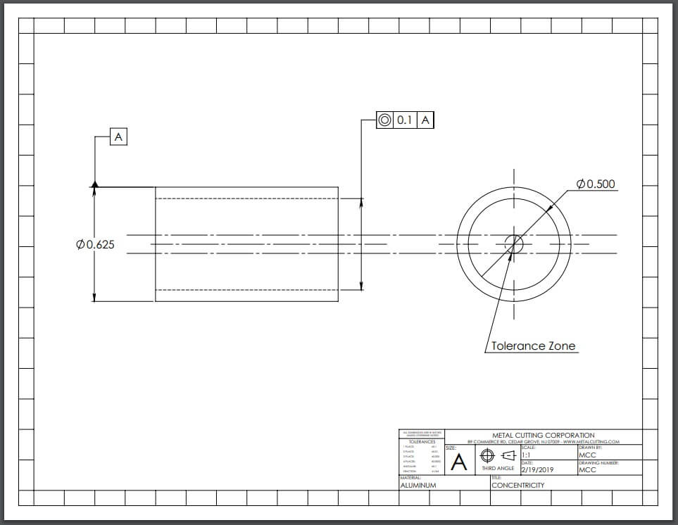
Concentricity Tolerance Zone
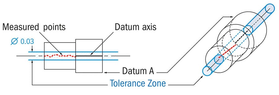
GD&T concentricity is defined by a cylindrical tolerance zone. The feature control frame provides a datum axis that serves as a reference point for constructing this zone. The diameter of the cylindrical zone represents the allowable tolerance value specified in the callout.
To ensure concentricity, the actual median axis of the part must be determined by calculating the midpoints of diametrically opposed points. When all these median points are connected, the resulting line represents the median axis. For the part to meet the requirements, all points along the median axis must fall within the cylindrical tolerance zone.
Concentricity Feature Control Frame
Feature control frames (FCFs) are utilized to communicate the manufacturing conditions, controls, and tolerances applied to a specific part feature. It is common for a single part to have multiple features that are toleranced by GD&T, and each feature’s tolerance is represented by its own FCF. The FCF is connected to the feature being controlled or its extension line using a leader arrow.
The feature control frame for GD&T concentricity can be explained as a layout consisting of three blocks. These blocks define the requirements for concentricity and specify that, “in relation to datum A, all median points of opposing elements on the cylindrical surface must fall within a cylindrical tolerance zone of 0.03”.
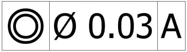
1. Geometric characteristic block
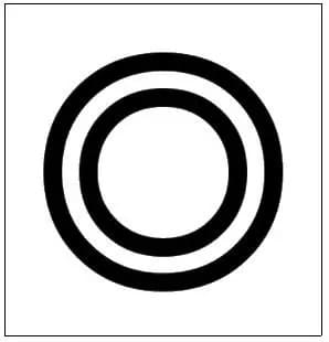
To put it differently, the first block within the concentricity feature control frame holds the geometric tolerance symbol that is applied to the feature. In this block, the concentricity symbol, represented by two concentric circles, is used to indicate and specify the required tolerance.
2. Feature tolerance block
The second block within the FCF provides details about the size and type of the tolerance zone that is applied. In the case of concentricity, this zone is cylindrical in shape and it is referred to as a diametral tolerance zone. In this block, the diameter symbol is used to specify the diameter of this cylindrical zone, which represents the tolerance value or the maximum allowable deviation for the median points of the part.
It should be noted that material modifiers cannot be utilized with concentricity due to the potential impact of bonus tolerance. This additional tolerance would enlarge the tolerance zone, resulting in a step function with varying diameters and sharp changes in the surface diameter.
3. Datum block
The third block in the FCF offers details about the datum element. Depending on the specific requirement, the datum element can be a center point, center line, or datum plane. In the case of concentricity, the datum element is a datum axis derived from a datum feature. It’s worth noting that in some instances, the concentricity feature control frame may include multiple datums, such as in the case of shafts with multiple diameters.
Concentricity vs. Runout vs. Position
Concentricity is a crucial requirement in various specialized applications that prioritize uniform mass distribution. However, due to the challenging and expensive nature of implementing concentricity, it is essential to be aware of alternative callouts that can meet the required specifications without compromising the desired outcome.
Runout and position are the two closely related callouts that can serve as substitutes for concentricity in many applications.
Concentricity vs. Position
Position in GD&T is a relatively straightforward callout that can specify the position and size of various features. In many cases, the position callout can serve as a suitable alternative to concentricity. When there is no requirement for precise mass distribution, standard hole sizes and positional tolerances are preferable over concentricity.
Concentricity vs. Runout
Concentricity and runout are two closely related geometric tolerances in GD&T that are used to assess the circularity and coaxiality of cylindrical or spherical features.
The challenge with measuring concentricity lies in determining the derived median axis of the part, which cannot be reliably calculated without the use of a computer.
On the other hand, runout can be easily measured from the surface of the part as it’s a tangible feature. Simple instruments like a V-block and dial indicator can provide accurate runout measurements. As a result, in certain cases, replacing concentricity requirements with runout can save time and cost, as runout is easier to measure and achieve.
While concentricity evaluates how well a cylindrical feature is centered on a theoretical axis, runout examines the extent to which the feature deviates from a perfect circle that is precisely centered on an axis of rotation. Runout is often defined as the sum of circularity and concentricity. In the case of a perfectly round part, the runout tolerance will equal the concentricity tolerance.
There are several key differences between concentricity and runout:
- Concentricity assesses the axis or center plane of a feature, whereas runout evaluates the circular path of a feature;
- Concentricity is employed to ensure rotational alignment and prevent vibration, while runout is used to evaluate surface shape;
- The GD&T symbol for concentricity and runout differs, as well as how they are represented on a drawing.
When Is Concentricity Required?
Due to its complexity, concentricity is typically reserved for parts that require high precision to function effectively.
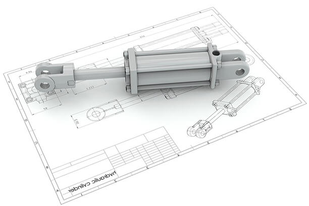
The importance of concentricity depends on the specific end use. For example, if a tube needs to fit inside an opening and another part needs to fit into the tube’s inner diameter (ID), then the outer diameter (OD), ID, and concentricity may need to align for all the parts to function together seamlessly.
On the other hand, if the application involves the passage of liquid or gas through a tube, concentricity may not be as critical since non-concentricity would not hinder the flow.
Nevertheless, even in cases where concentricity is not crucial, it may still be necessary to determine the acceptable level of deviation from concentricity for the OD/ID. For instance, when a liquid or gas flows through a tube under pressure, specifying a minimum acceptable wall thickness becomes important to prevent breakage in thin areas of the non-concentric tube wall.
The material selection can also be related to concentricity and the minimum/maximum wall thickness to some extent. For example, if you have opted for welded tubing that will undergo grinding to create a part, it may be important to specify a minimum thickness to prevent excessive grinding and potential weld breakage.
Similarly, if the tube will be used in an application involving the movement of liquid under high pressure, choosing a seamless material that is drawn instead of welded might be a more suitable choice to minimize the risk of breakage. However, if the tube will simply release air into the environment, using seamless tubing may be considered excessive in terms of engineering.
Challenges of Measuring Concentricity
Determining concentricity and verifying if the specified OD and ID have been achieved faces certain difficulties. In addition to establishing the theoretical central axis, measuring concentricity requires:
- Taking numerous measurements across multiple cross-sections;
- Accurately mapping out the surface and identifying the median points of the cross-sections;
- Plotting these points to check if they fall within the cylindrical tolerance zone.
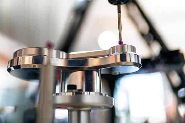
While a micrometer or optical comparator can be used to measure concentricity in some cases, the most accurate method involves employing a coordinate measuring machine (CMM) or other computer measurement devices. However, using CMM can be time-consuming and result in additional costs.
Another challenge arises from the fact that current micromachining techniques have led to the production of increasingly smaller parts. For example, in the case of precision-cut tubes used in medical devices, the difficulty lies in how to measure the concentricity of two diameters in extremely small tubing.
How to Measure Concentricity
The measurement process for concentricity is a primary reason why many designers and machinists tend to avoid it. Taking the required measurements is time-consuming, expensive, and challenging.
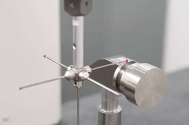
The inspector is required to construct the actual central axis of the part by connecting the center points of consecutive circular cross-sections. This is why achieving accurate concentricity measurements necessitates the use of a coordinate measuring machine (CMM) or other computer-assisted measurement methods such as an optical shaft measuring system or a laser micrometer with a concentricity extension.
Engineers often use a dial gauge to measure the difference between the highest and lowest points on the surface, mistakenly thinking they are measuring concentricity when they are actually measuring runout. As we discussed earlier, runout can only be equal to concentricity if the section being measured is a perfect circle, which is rarely the case. Passing runout measurements as concentricity can introduce circularity errors into the concentricity tolerance.
Now, let’s briefly go through the step-by-step process for measuring concentricity.
Using a CMM to measure concentricity
Measuring concentricity using a CMM involves four steps:
Step 1: Securing the part and establishing the datum axis (theoretical axis)
In this step, the part is carefully positioned to restrict all degrees of freedom, ensuring that the entire cylindrical surface is accessible for measurement. It’s important to choose a position that eliminates the need for repositioning during the measurement process.
Establishing the datum axis involves selecting the bearing end of the shaft as the reference axis, as the rotation of the assembly will be directed from that end.
Step 2: Determining the center point for a single cross-section
In this step, the control surface is plotted using a CMM stylus. Multiple pairs of diametrically opposed points are needed at each cross-section of the cylindrical part. It is recommended to have a minimum of three such pairs at every cross-section. These pairs of points will result in three distinct median points (unless some points coincide). The average of these three median points is then selected as the center point for that particular cross-section.
Step 3: Repeating the process for multiple cross-sections along the length of the cylindrical part.
In this step, the center point for each cross-section is calculated, and when these points are connected, the measured axis or actual central axis of the part is obtained. This axis is also referred to as the derived axis.
Step 4: Verifying if the measured axis falls within the designated tolerance zone
The fourth step entails checking whether the measured axis falls within the specified tolerance zone in reference to the datum axis. Every point on this axis must lie within the cylindrical tolerance zone specified in the feature control frame (FCF).
Application Areas of Concentricity
Although most experienced engineers recognize that concentricity tolerance should only be used when absolutely necessary, there are still various applications that require it. Here are a few examples:
- Medical-grade tubing
Concentricity is also utilized to regulate the wall thickness of tubing in medical devices. Since these parts can be extremely small, achieving a high level of precision is crucial for producing acceptable products. - High-pressure piping
Concentricity tolerance is frequently employed in the manufacturing of high-pressure piping. These parts require a minimum wall thickness to avoid any weak points along the length of the tube, which could result in rupture under high pressures. - Precision ball bearings
High precision parts used in various industries, such as ball bearings, require tight tolerances to minimize energy losses and ensure proper operation. Concentricity tolerance is employed between different components of a ball bearing to ensure that it meets the required specifications. - Transmission gears
The production of transmission gears necessitates concentricity to align the axes perfectly, preventing lateral movement and reducing wear and tear. However, in certain situations, runout might provide adequate accuracy.
FAQs
Conclusion
Even though the application and measurement of concentricity can be challenging and costly, it is essential in maintaining the integrity and performance of certain precision components. Each geometric tolerance, including concentricity, offers unique benefits and limitations, and it’s up to engineers to make informed decisions on when and how to implement them in their designs and manufacturing processes.
Turn to Runsom Precision for Custom Precision CNC Machined Parts with Tight Tolerance
If you require CNC machined parts with tight tolerance and high quality, you can turn to Runsom Precision. We’re an expert in precision CNC machining services for custom parts in various materials. Our professional specialists have extensive experience in manufacturing custom CNC machined parts with a full set of highly advanced equipment and testing instruments such as the coordinate measuring machine (CMM), enabling all these parts to comply with the required tolerance and standards. Just simply upload your files and get an instant quote today!
Other Articles You May Be Interested in: