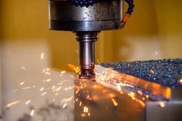


CNC machining, known for its high accuracy and precision, is a prevalent subtractive manufacturing technique globally. It owes its success to the CNC-controlled relative motion between the workpiece and the cutting tool. This motion can be categorized as cutting and feed motions, with cutting speed and feed rate used as measures.
So, what exactly are cutting speed and feed rate, what’s the difference between cutting speed and feed rate? And how do these parameters impact the success of manufacturing projects? Follow us to find out more.
What is Cutting Speed?
Cutting speed is commonly referred to as the speed at which the cutting tool and the workpiece surface move relative to each other. It can also be defined as the linear distance, measured in meters per minute or feet per minute, that the cutting tool material passes over the surface of the workpiece during a cutting process.
The cutting speed significantly determines various key parameters in CNC machining, including power consumption, cutting temperature, and tool life. This influence represents a significant difference between feed rate and cutting speed. The specific values of cutting speed will vary depending on the material being machined, such as aluminum, high carbon steel, low carbon steel, or plastics.
Factors to Be Considered for Optimum Cutting Speed
Ensuring an optimal cutting speed is essential for achieving the desired output in CNC machining. The ideal cutting speed for a specific CNC machining process involves optimizing the following aspects:
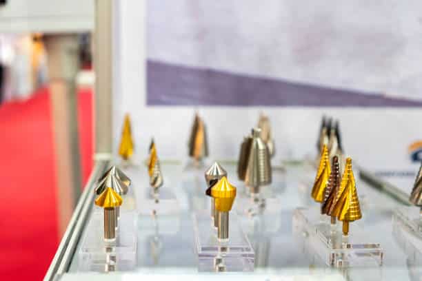
1. Material of the Cutting Tool
The CNC machine employs various cutting tools, which can be composed of either soft or hard materials. The optimal cutting speed significantly depends on the strength of the cutting tool. For example, cutting tools made from high-strength materials like diamond and carbon boron nitride are suitable for high-speed cutting, while cutting tools made from softer materials are better suited for low-speed cutting.
Below is a table that outlines some common cutting tool materials and their recommended range of allowable cutting speeds.
| Cutting tool material | Cutting speed (m/min) |
| High-speed steel | 30-50 |
| Cemented carbide | 60-100 |
| Ceramics | 300-600 |
| Carbon boron nitride | 300-600 |
| Diamond | > 800 |
2. Workpiece Hardness
The hardness of a material refers to its ability to resist deformation from scratching, abrasion, and indentation. For harder materials to be cut, special precautions must be taken to prevent tool performance degradation during the machining process. Specifically, workpieces are harder, the cutting speeds should be slower. To illustrate, titanium requires a greatly lower cutting speed compared to aluminum.
Here is a chart with the allowable cutting speed ranges for various materials in different CNC machining processes.
| Material | Turning | Drilling | Reaming | End Milling(Roughing) | |
|---|---|---|---|---|---|
| Aluminum | 400-1000 | 250-600 | 100-300 | 600 | |
| Brass | 225-300 | 150-300 | 130-200 | ||
| Bronze | 150-225 | 100-250 | 75-180 | Medium: 250Hard: 125 | |
| Cast Iron | Soft | 100-150 | 75-150 | 60-100 | 60 |
| Medium | 75-120 | 70-110 | 35-65 | ||
| Hard | 50-90 | 60-100 | 20-55 | 50 | |
| Copper | 100-200 | 60-100 | 40-60 | ||
| Magnesium | 600-1200 | 300-650 | 150-350 | ||
| Stainless Steel | Free machining | 100-150 | 65-100 | 35-85 | 304: 5517-4PH: 35 |
| Other grades | 40-85 | 15-50 | 15-30 | ||
| Carbon and Alloy Steel | Free machining | 125-200 | 100-145 | 60-100 | Low C: 754140: 504340: 50 |
| less than 0.3% C | 75-175 | 70-120 | 50-90 | ||
| 0.3% to 0.6% C | 65-120 | 55-90 | 45-70 | ||
| more than 0.6% C | 60-80 | 40-60 | 40-50 | ||
| Titanium | 25-55 | 30-60 | 10-20 | Ti-6AI-4V: 25 | |
Note:
- This table is specifically for high-speed steel tooling. If you are using a carbide cutter, remember to adjust the cutting speed based on the hardness of the cutting tool. For instance, you may need to multiply the listed speeds by a factor of 2 to 4. In addition, when working with carbon steel tools, the cutting speed should be lower.
- All the speeds are in surface feet per minute (SFM).
3. Tool Life
Higher cutting speeds can cause softer cutting tool materials to wear out quickly, resulting in shorter tool life. Therefore, considering the tool life is another crucial factor when determining the cutting speed. Tool life refers to the period during which the cutting tool remains effective and significantly impacts the accuracy of the workpiece and the chosen cutting speed.
What is the Feed Rate?
The feed rate is referred to as the distance traveled by the cutting tool during one revolution of the spindle. It may also be called the cutting tool engagement speed and is typically measured in units such as inches per minute or millimeters per minute in milling operations.
For boring and turning operations, the feed rate can be measured in units such as inches per revolution or millimeters per revolution. The specific values of the feed rates will vary depending on factors such as the type of material being machined (aluminum, stainless steel, steel, wood, etc.), the type of cutting tool material (HSS cutting tool, ceramic, cermet, etc.), and other cutting factors like surface finish and the CNC machine performance.
The aesthetic quality of the machined products is largely affected by the feed rate, This is why the feed rate serves as a critical aspect in CNC machining processes.
Factors to Be Considered for Optimum Feed Rate
The feed rate in CNC machining is closely related to various aspects of the process, including safety, product quality, tool life, and productivity. To determine the ideal feed rate value, several factors need to be taken into account:
1. Cut Width
Chip thinning is considered a manufacturing defect that can prolong the lead time. When the cut width is less than half the diameter, chip thinning occurs, resulting in a decrease in the chip load or the amount of material cut by the tool in one revolution. To mitigate the impact of chip thinning, increasing the feed rate is advisable, as it can enhance productivity and extend the tool life.
2. Cutting Tool Geometry
In addition to the feed rate, the tool geometry can also have an impact on the surface finish of the products. If the tool geometry allows, opting for a higher value can be advantageous.
3. Machine Tool Capability
A higher feed rate can result in increased cutting force and vibrations. So select the appropriate feed rate on account of the machine tool‘s ability to absorb and transmit these higher forces and vibrations.
4. Surface Finish
Lower feed rates can result in a better surface finish. For rough cuts, a higher feed rate can be used. As an example, a feed rate of 0.01-0.05mm/rev can be considered for finishing operations, while a feed rate of 0.1-0.3mm/rev may be suitable for rough turning operations.
5. Productivity
To achieve higher productivity rates, it’s possible to increase the feed rate at the expense of surface quality. Alternatively, by keeping the feed rate stable, it is feasible to increase the cutting speed.
6. Feed Rate Limit
Machine tools typically have a feed-by-feed rod that operates within specific minimum and maximum limits. However, for conventional lathe machine tools, there are only a limited number of feed rate options available within the specified range.
Cutting Speed vs. Feed Rate: Their Difference in CNC Machining
While both feed rate and cutting speed have a great impact on the overall performance of a machine, they represent distinct concepts. To achieve optimal results from a CNC machine, it’s necessary to comprehend the difference between these two.
| Parameter | Cutting Speed | Feed Rate |
| Generatrix and Directrix | Cutting speed generates the directrix. | The feed rate generates the generatrix. |
| Units of Motion | Measured in meters per minute (m/min) or feet per minute (ft/min) and denoted by Vc. | Measured in meters per revolution (mpr) or inches per revolution (ipr) and denoted by s or f. |
| Chip Direction | No effect on deviating from the orthogonal chip direction. | Great effect on the actual chip flow direction. |
| Motion | Cutting motion generates cutting speed. | Feed motion generates feed rate. |
| Cutting Force and Power Consumption | Cutting speed affects these parameters on a larger scale. | Feed rate influences these parameters on a smaller level. |
| Surface Roughness and Scallop Marks | Not directly related to the scalloping or marks produced on the machined surface. | Significantly related to the scalloped marks on the finished surface. |
| Cutting Temperature, Tool Life, and Tool Wear | Greatly impacted. | Less impacted. |
1. Tool Motion
Feed rate refers to the speed at which the tool travels through the workpiece, while cutting speed refers to the speed at which the cutting edge of the tool moves. To put it simply, the feed rate measures the speed of the tool as it moves through the material, while the cutting speed measures the actual speed at which the tool cuts.
2. Directrix & Generatrix
The cutting speed, denoted as Vc, provides the generatrix and is typically measured in m/min or ft/min. The feed rate, denoted as s or f, provides the directrix and is generally measured in mm/rev or mm/min.
3. Chip Direction
The cutting speed does not cause the chip direction to be orthogonal. However, the feed rate typically has an impact on the flow and direction of the actual chip.
4. Cutting Temperature, Tool Wear & Tool Life
The feed rate has a minimal impact on factors such as cutting temperature, tool wear, and tool life. However, the cutting speed significantly affects these factors.
5. Cutting Force & Power Consumption
The cutting speed has a significant impact on both the cutting force and power consumption during the machining process. Conversely, the feed rate has a relatively smaller impact on these parameters.
6. Surface Roughness & Scallop Marks
The presence of scallops or feed marks on the machined surface is directly related to the feed rate and serves as a representation of the surface roughness, while the cutting speed is irrelevant to these machined marks.
How to Calculate Cutting Speed and Feed Rate?
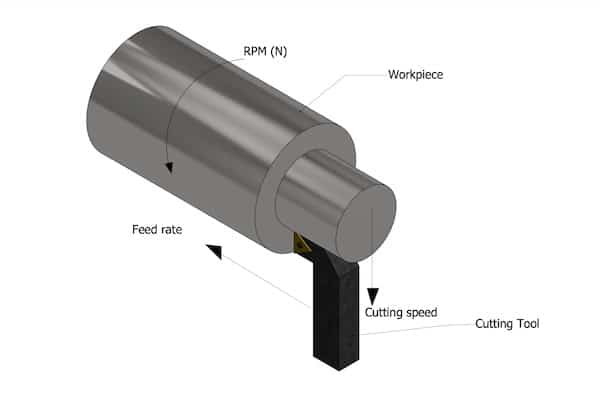
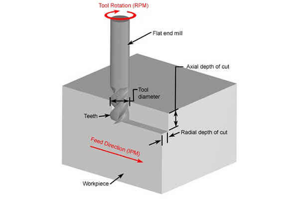
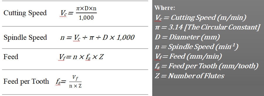
The picture below presents the essential parameters for calculating the cutting speed and feed rate. In order to determine these values, the spindle speed serves as the fundamental requirement. The feed rate is determined using two formulas. Firstly, the feed per tooth is calculated, and this value is then used to determine the feed rate of the cutting tool.
What’s the Importance of Cutting Speed and Feed Rate in CNC Machining?
- Speeds and feeds contribute to the machining process as they determine both the rate and amount of material removal.
- The lifespan of a tool can be significantly influenced by the speeds and feeds used during machining.
- Cutting speed has a direct influence on cutting temperature. Higher cutting temperatures can negatively impact factors such as tool life and surface roughness.
- Compared to processing softer materials like aluminum or resin, the adverse effects of incorrect speeds and feeds become more visible when working with harder materials such as titanium or Inconel, where there is a narrower margin for error.
- Even a small discrepancy between the speed and feed rate can quickly lead to the breaking of the cutting tool.
- An optimal feed rate is necessary to achieve superior surface roughness. Using high tool rates and spindle speeds can result in chatter marks appearing on the material surface.
Other Key Factors to Be Considered
Non-Linear Path
Typically, the feed rate involves linear motion i.e., the distance traveled in a line. However, there are instances where feed rates are considered along an arc or circular interpolation path, such as for outer diameter or inner diameter machining.
As the depth of the cut becomes larger, the angle of engagement on the tool increases, leading to a non-linear path. The degree of tool engagement is higher when working on internal corners compared to external corners.
Spindle Speed Limit
To determine the cutter speed in RPM, it’s necessary to know the surface feet per minute (SFM) based on the material and cutter diameter. In some cases, especially when working with small tools or specific materials, the calculated speed may be impractical.
In such situations, the machinist can opt to run the tool at the highest speed achievable by the machine while maintaining the required chip load for the diameter. This approach allows for the attainment of optimal parameters at the machine’s maximum speed.
Interaction of Cutting Velocity and Feed Rate
During the machining process, the cutting tool applies compression to the surface of the workpiece and eliminates a thin layer of material in the form of a chip. A desired relative velocity between the workpiece and cutter is necessary to transmit the required compressive force. The cutting velocity is primarily responsible for generating this relative velocity, helping predict material removal.
To visualize the amount of material that is being removed from the entire surface of the workpiece, there is an additional synchronized motion called the feed motion. The specific direction and type of this feed motion can vary depending on the milling operation being performed. These simultaneous actions of the feed rate, cutting velocity, and feed motion collectively fulfill the fundamental requirements of machining.
FAQs
Conclusion
To optimize various aspects of CNC machining parameters such as tool life, power consumption, time, and surface roughness, it is essential to determine the optimal cutting speeds and feeds. Understanding how the cutting speed and feed rate interact with each other is key to achieving accurately machined parts.
Work with Runsom Precision for Your CNC Machining Needs
Besides feed rate and cutting speed, there are various other factors that can enhance the efficiency of the CNC machining process. However, you can alleviate concerns regarding these factors by working with a trusted and experienced manufacturer like Runsom Precision. Our team of experienced engineers and machinists is proficient in CNC machining services and dedicated to meeting diverse machining requirements, guaranteeing top-quality machined parts consistently. Contact us now to get an instant quote for all your CNC machining needs.
Other Articles You May Be Interested in: