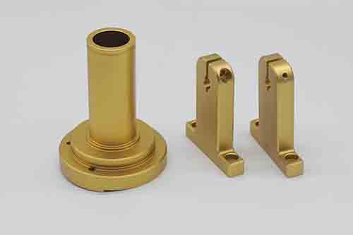
Computer Numerical Control or CNC Machining is a subtractive manufacturing technique that uses CNC machines to produce complex geometries with highly precise tolerances. This manufacturing process usually involves the use of a computer-controlled work tool to remove material from the stock of material and to produce the desired product. While CNC machining can produce parts that are highly precise in dimensions, the process produces parts that have a specific texture. This texture is called surface roughness and is very important to the functionality, performance, and durability of the part produced.
Surface Roughness
Surface Roughness, or simply roughness, is the measure of the irregularities in a surface. It is the most measured and quantified aspect of the surface finish, and this is the reason most technicians refer to surface roughness as surface finish.
After CNC machining, the roughness of the machined part influences the application, operation, and life of the part. Surface roughness impacts the friction, lubrication requirements, wear and tear as well as interconnectivity, mating, stress concentrations, and noise levels. The value of surface roughness, therefore, is paramount and extra precaution should be taken while performing CNC machining. The value of surface roughness of the machined part is not random but is controlled while performing CNC machining. An industry-standard value usually in the range of 25um to 0.05um is specified for the part. However, lowering the surface roughness value can make the CNC machining costlier and inefficient.

Surface Finish – Units
The surface finish of a machined part is described using some parameters which are called surface finish units. These units help design engineers as well as technicians to understand the desired surface finish. These units are:
Average Roughness, Ra
The most common unit to quantify roughness is the Average Roughness (Ra). Average Roughness (Ra) is an arithmetic average between the peak of the roughness profile and a mean line. Since it is an arithmetic average, average roughness eliminates the effect of any outliers in the form of occasional spikes.
However, different roughness profiles can have the same average roughness therefore to completely describe surface finish, we need some additional parameters.
Maximum Roughness Depth, Rmax
Maximum roughness Depth is the highest vertical distance between the peak and lowest trough in a selected sample length. Since it is the highest value, maximum roughness depth is not an accurate description of surface roughness since any scratch can result in an increased value of surface roughness than the actual value.
Mean Roughness, Rz
This surface finish unit is preferred across Europe over average roughness. Instead of measuring the distance between the peak and mean line, mean roughness measures the distance between the few highest peak heights and depths of roughness profile in the sample length and then averages the value. This parameter, however, is not an accurate one since it relies on the highest peaks and depths.
Root Mean Square, RMS
Root mean square, as the name indicates, is the surface finish unit that is similar to the average roughness parameter but instead of averaging the distance, it takes the average of the square of the distance between the peak height and mean length and then takes the square root of the value. This value represents the surface roughness in the form of a sinusoidal wave, each representing the distance from the mean line.
Root mean square is, however, an approximation of the surface roughness and is not an actual representation of the final surface finish. It relates to average roughness Ra, by a factor of 1.1.

Conversion Table
| Ra (micrometers) | Ra (microinches) | RMS (microinches) | CLA (N) | Rt (microns) | N | Cut-off Length (inches) |
| 0.025 | 1 | 1.1 | 1 | 0.3 | 1 | 0.003 |
| 0.05 | 2 | 2.2 | 2 | 0.5 | 2 | 0.01 |
| 0.1 | 4 | 4.4 | 4 | 0.8 | 3 | 0.01 |
| 0.2 | 8 | 8.8 | 8 | 1.2 | 4 | 0.01 |
| 0.4 | 16 | 17.6 | 16 | 2.0 | 5 | 0.01 |
| 0.8 | 32 | 32.5 | 32 | 4.0 | 6 | 0.03 |
| 1.6 | 63 | 64.3 | 63 | 8.0 | 7 | 0.03 |
| 3.2 | 125 | 137.5 | 125 | 13 | 8 | 0.1 |
| 6.3 | 250 | 275 | 250 | 25 | 9 | 0.1 |
| 12.5 | 500 | 550 | 500 | 50 | 10 | 0.1 |
| 25.0 | 1000 | 1100 | 1000 | 100 | 11 | 0.3 |
| 50.0 | 2000 | 2200 | 2000 | 200 | 12 | 0.3 |
Surface Finish – Measurement Techniques
Following methods can be used to measure surface roughness:
Direct Method
This method makes use of a stylus, held perpendicular to the surface, to measure surface roughness. The stylus generates the roughness profile directly and from this profile, the values of various surface units can be calculated.

Non-Contact Technique
As the name suggests, the non-contact measurement technique, in contrast to the direct method, uses light or sound to generate the roughness profile. Instead of a stylus, this process uses optical and vocal sensors. A light or sound wave is bombarded on the surface which then reflects it, this reflected wave can help assess the profile of the surface roughness.
Comparison Technique
This method uses the comparison of a sample of known surface roughness with the samples of unknown surface roughness. The technician can then compare the surface roughness of both samples using different visual techniques and analyze them to assign value to the material. This technique is generally not accurate due to its high dependence on human subjectivity.
In-Process Technique
The use of electromagnetic induction to measure surface roughness is called the in-process technique. The magnetic induction is used to measure the distance between the peaks and depths of the roughness profile. However, this method is useful only for magnetic materials.


