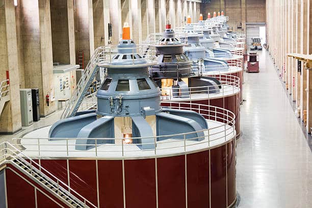

5-axis CNC machining offers a significantly more efficient method for producing a diverse array of components, extending beyond intricate aerospace parts. This approach addresses the machining requirements for impellers, blades, marine propellers, large generator rotors, wind turbine blades, heavy-duty diesel engine crankshafts, and more.
Here, we’ll discuss the 5 axis CNC machining of impeller: why use it, challenges and solutions during machining, and what you should consider in the machining process.
What is an Impeller?
An impeller serves as the rotating element within a centrifugal pump, responsible for propelling fluid outward from the center of rotation, thereby transmitting energy from the pump’s driving motor to the fluid being conveyed. The achieved velocity of the impeller is converted into pressure as the fluid’s outward movement is confined by the pump casing.
Typically, an impeller takes the form of a short cylinder featuring an open inlet (referred to as an eye) to receive incoming fluid, vanes to propel the fluid radially, and a splined, keyed, or threaded bore to accommodate a drive shaft.
The flow dynamics within the impeller are intricate, often operating under conditions of high temperature, high pressure, and exposure to corrosive environments. The design and quality of the impeller play a vital role in the performance of the turbocharger. Factors such as the vane shape, vane count, and rotational speed all influence the pressure and flow capacity that the impeller can generate.
Fundamental criteria for an effective impeller include:
- The capability to furnish substantial power output.
- Maintaining minimal airflow resistance as it passes through the impeller, emphasizing high efficiency.
- Ensuring that each parameter is suitable for the airflow exiting the impeller to minimize adverse effects on components downstream.
Types of Impellers
Open Impeller
An open impeller features vanes that are directly mounted onto a shaft and affixed to a central hub. These vanes lack an enclosing wall, rendering open impellers less robust than closed or semi-closed variants. However, open impellers are typically easier and faster to clean and maintain. They are commonly employed in smaller pumps and those designed for handling suspended solids.
Semi-Closed Impeller
Semi-closed impellers include a rear wall that enhances impeller strength. Generally used for handling liquids or solid materials, semi-closed impellers may experience diminished performance. Nevertheless, they offer the advantage of effectively managing solid substances.
Closed Impeller
Closed impellers are encompassed by front and back walls, heightening their structural integrity. Primarily utilized in larger pumps, they are suitable for applications involving suspended solids.
These impeller types are frequently utilized in applications involving clear liquids, proving less effective in handling solids and presenting challenges in case of blockages. Manufactured using high-quality raw materials and cutting-edge technology under international standards, these impellers assure reliable performance.
How to Machining Impeller?
Machining the impeller involves various steps, including roughing, semi-finishing, and finishing:
Roughing
Various roughing options are available, including multiple normal cuts to the surface, mid-axis cuts along the device axis, full 5-axis dive roughing, and adaptive roughing.
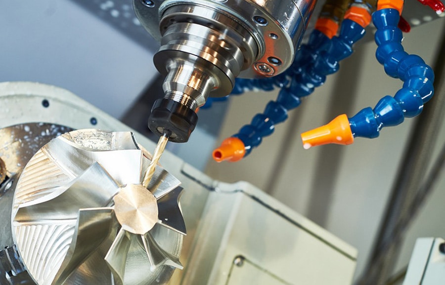
To achieve a superior finish using a 5-axis machine, the tool must be angled specifically to the surface area.
The impeller processing process is segmented into several processing methods, such as impeller rough machining, blade surface mid-processing, blade surface finishing, and runner surface finishing.
Rough machining aims to efficiently and swiftly remove excess material, and it is also the method that best exhibits the effectiveness of impeller machining. This includes cavity milling and multi-blade roughing.
Semi Finishing
The toolpaths for semi-finishing and finishing are essentially identical, differing only in the amount of remaining material and the step-over value. It is important to ensure that enough material is left for the finishing process. When carried out accurately, the finish cut will be precise and free of vibrations, enabling smooth and controlled cutting, even on extremely thin blades. Tapered-end ballnose cutters are the preferred choice due to their maximum rigidity.
Finishing
The purpose of finishing is to achieve a high-quality surface. This is closely tied to tool selection and the combination of tool speed and feed, as demonstrated in Z-level finishing.
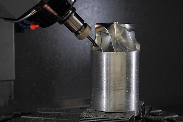
The finishing of impeller blades poses a significant challenge. Impeller blades are often thin, warped, varying in height from one end to the other, and closely spaced. It is important to maintain a cut pattern parallel to the central surface and to execute the entire blade cut in one continuous movement to avoid unwanted tool marks on the workpiece.
Improving the efficiency of impeller processing primarily involves enhancing roughing efficiency. The use of the five-axis impeller roughing setting allows for the realization of five-axis CNC machine roughing for the impeller, ensuring even material removal, a relatively smooth processing path, and improved processing efficiency.
Why Choose 5 Axis CNC Machining for Impeller Machining?
5-axis CNC milling and turning machining are employed to fabricate intricate surfaces on components that require 5-axis machining. This process significantly influences industries such as aircraft, aerospace, scientific research, precision equipment, high-precision medical equipment, optical equipment, environmental protection, and others.
Currently, a 5-axis CNC machining center stands as the sole method available to address the machining of impellers, blades, marine propellers, heavy generator rotors, turbine rotors, large diesel engine crankshafts, and similar components.
- 5-axis machining features high efficiency and precision.
- The additional range of motion provided by 5-axis machining enables the creation of intricate and diverse shapes without compromising precision.
- Components can be completed solely on the 5-axis machine, eliminating the need for transferring workpieces across multiple workstations and ensuring higher accuracy in the finished parts.
- The utilization of 5-axis technology allows impellers to be completed in a single setup, reducing the need for multiple setups and fixture preparation, resulting in time and cost savings.
- 5-axis machining contributes to achieving exceptional surface finishes, thereby enhancing the overall quality of the parts.
- Shorter cutting tools can be employed to achieve higher cutting speeds and reduced tool vibrations, leading to increased precision.
Challenges and Solutions in CNC Machining Impeller
This part will analyze the difficulties and relevant solutions to CNC machining of impellers in given situations.
Challenges
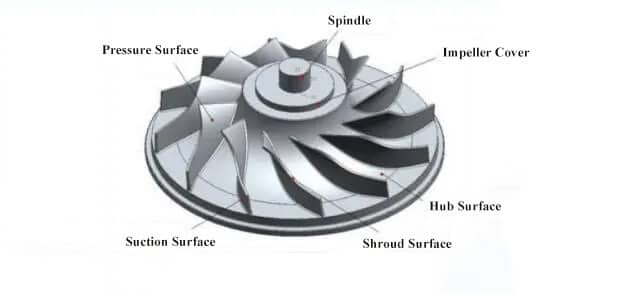
The typical structure of an impeller consists of multiple sets of blades evenly distributed on the curved surface of the hub. Each set of blades may contain a single blade or multiple blades, with the former referred to as equal blades and the latter as crosswise blades. This arrangement contributes to the overall impeller effect, as depicted in the following image.
Furthermore, a significant amount of material needs to be removed between the blades. To meet aerodynamic requirements, the blades often feature substantial torsion angles and radii at their roots, complicating the machining process for the impeller. In summary, the challenges in impeller machining can be outlined as follows:
- Tapered Machining Path: The machining path for the impeller is tapered, and the blade lengths are relatively long and delicate.
- Thin Walls: The impeller is characterized by thin walls, making it highly susceptible to deformation during the machining process.
The narrowest part of the blade groove has a depth exceeding 8 times the diameter of the end mill, and the adjacent blades are exceptionally small, increasing the susceptibility of small-diameter end mills to breakage. Furthermore, precise control of the cutting depth represents a pivotal technological aspect.
Solutions
In this case, the overall impeller surface exhibits a free-form configuration with a narrow flow path, significant blade twisting, and noticeable backward tilt. These factors contribute to substantial potential interference among the parts during the machining process, rendering the machining task quite challenging. Given that some blades incorporate smaller blades, machining the curved surfaces area by area becomes necessary to prevent part interference. Consequently, maintaining consistency in the impeller’s surface after completion proves to be a challenging endeavor.
Machining an impeller entails consideration not only of geometric factors such as size, shape, and position but also of mechanical, physical, and chemical aspects. Before machining, an impeller blank must undergo careful inspection for any damage. The impeller blades must exhibit exceptional surface quality, with high precision requirements for the surface of the blade, the surface of the hub and the blade. The surface roughness should be below Ra0.8μm. The smooth transition of the cross-section and the uniform texture of the blades dictate the direction and path of the end mill.
During impeller operation, achieving high dynamic balance is critical to minimizing vibration and noise. Consequently, the symmetry of the impeller must be considered during the machining process. In CAM programming, blade and runner parameters can be configured to achieve impeller symmetry. Additionally, efforts should be made to minimize errors stemming from clamping or end mill changes.
Considerations for CNC Machining of Impeller
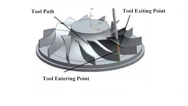
To avoid interference, it requires careful consideration of the axis of the cutting tools. Particularly during the feeding and exiting of the end mills, adherence to the specified exit setup is crucial. Furthermore, when chamfering and filleting the impeller blades, the correct distance and direction for entry and exit must be established, as illustrated in the photo below:
- Proper positioning of the workpiece is essential to prevent collisions between the cutting tools and fixtures.
- When clamping the workpiece onto the machine, the travel distance of the CNC machine should be taken into account to avoid over-travel.
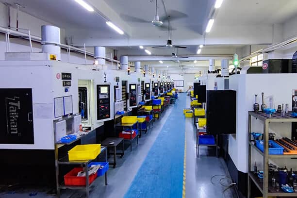
Custom CNC Machining of Turbocharger Impeller Solution at Runsom Precision
If you seek advanced 5-axis CNC machining services, you can rely on Runsom Precision. The engineers at Runsom Precision possess decades of expertise in custom CNC machining of turbocharger impeller projects, specializing in the manufacture of intricate rotational components featuring multiple blades across a diverse array of materials, adhering to precise dimensions and rigorous specifications, including but not limited to blisks, impellers, and individual blades. Our capabilities encompass high-speed simultaneous 5-axis milling of turbocharger impellers, aero-engine spacers, compressor impellers, turbines, pumps, blades, and vanes.
We stand prepared to propose more efficient manufacturing methods, processes, and design alterations tailored to meet your requirements while simultaneously reducing production costs. Reach out to us to obtain an instant quote and start your impeller CNC machining projects today!
Learn more about our Custom Impeller CNC Machining Services
Other Articles You May Be Interested in: