
It is recognized that manufactured products can never be an exact match to their theoretical designs. The actual size of the product often differs from the original intended design. The purpose of Geometric Dimensioning and Tolerancing (GD&T) is to control and limit this variation.
In GD&T, the tolerance called “Position” is commonly used as a guideline for manufacturers in the CNC turning and milling industry. However, many people tend to refer to this GD&T symbol as “True Position.” In reality, according to the ASME Y14.5 standard, the term for this symbol is simply “Position.” So, how are these terms defined, and how to distinguish them?
Here, we will cover the fundamentals of position and true position, the difference between position and true position, and how to use, calculate, and measure the true position.
What is the Position in GD&T?
The position in GD&T, also known as Geometric Dimensioning and Tolerancing, defines acceptable ranges of variation for the location of features on a part. This tolerance is of great importance for controlling the location of critical features like holes, bosses, pins, and other geometric elements.
The position tolerance consists of two key components: the tolerance value and the datum reference. The tolerance value represents the maximum allowable deviation from the true position, while the datum reference serves as the point, line, or plane used as a basis for the measurement.
Position tolerance can be applied to both two-dimensional and three-dimensional features, and various measurement tools such as coordinate measuring machines (CMMs), laser scanners, or optical comparators can be used to evaluate it. These tools help ensure that the features are located correctly for effective part function and assembly.
What is True Position in GD&T?
In GD&T, the true position refers to the precise coordinate or location that represents the nominal value of a feature. It offers more detailed information about both the position and orientation of the feature compared to position tolerance. The true position defines a circular tolerance zone, centered on the true position, with a diameter representing the maximum allowable deviation from the intended location. This positional tolerance is specified in the feature control frame.
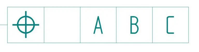
In the ASME Y14.5 standard, the crosshair symbol (⌖) is used to represent position, but now it is also used to denote true position in GD&T. The true position symbol is applied to features that require a high level of positional accuracy, such as holes, pins, or other elements that need precise alignment or mating with other parts. It ensures that the feature falls within the specified tolerance zone relative to the datum or reference point.
Understanding Position and True Position
To understand the distinction between true position and position tolerance, let’s imagine a scenario of throwing darts at a bullseye. Our goal is to hit the precise center of the bullseye, which represents the true position. However, in reality, it’s highly unlikely that all the darts will hit the exact center. The question then arises: how much deviation from the exact center is considered acceptable? This allowable deviation is defined by the position tolerance.
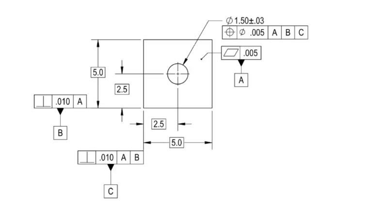
Figure 1 illustrates position controls the location of the hole in the center of a part, while true position indicates the specific location of the axis of the hole which is determined by the basic dimensions of being 2.5″ from the bottom of the part (Datum Feature B) and 2.5″ from the left side (Datum Feature C).
To define the tolerance on this location, the feature control frame for the hole is utilized. This frame indicates that the hole has a diameter-based position tolerance of 0.005″.
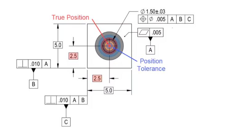
To better understand the concept, figure 2 visualizes the throwing darts scene. Note that the highlighted basic dimensions in red indicate the true position, i.e. hitting the center of a bullseye exactly.
To represent the position tolerance, we can see a blue ring surrounding the true position. Imagine this as the acceptable range around the true position that allows the feature to pass inspection. In other words, when measuring the axis of the hole, it must fall within this designated diametrical position tolerance zone.
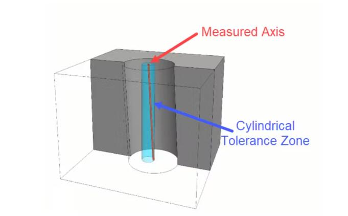
Additionally, it’s important to note that we are not solely examining the axis as a simple two-dimensional location. In Figure 3, a 3-dimensional model is shown to emphasize that the measured axis of this hole must fit entirely within the cylindrical area created by the specified diametrical position tolerance.
Differences Between Position and True Position
The true position represents the precise and specified location of a feature, determined by basic dimensions or other means. On the other hand, position tolerance defines the permissible variation or deviation of the feature from its true position.
1. Calculation method
The calculation of position tolerance involves measuring the distance between the actual location of the feature and its intended location, projecting this onto a plane that is parallel to the specified datum.
In contrast, the calculation of true position tolerance requires measuring the distance between the actual location of the feature and its intended location, projecting this onto a cylinder. The diameter of this cylinder corresponds to the specified tolerance value.
2. Range of deviation
Position tolerance establishes the maximum acceptable deviation of the feature’s location along the X and Y directions.
On the other hand, true position sets the maximum permissible deviation in any direction from the true position.
3. Datum reference
Position tolerance necessitates a minimum of two datum references to define the acceptable variation in the feature’s location.
In contrast, true position only requires a single datum reference to determine the permissible deviation from the true position.
4. Complexity
True position is typically more intricate and challenging to implement compared to position tolerance. This complexity arises from the requirement to calculate variations in all directions from the true position.
5. Application
Position tolerance is typically employed when the location of a feature holds significance, but its orientation is not of utmost importance.
True position comes into play when both the location and orientation of the feature are crucial.
Below, the video provides a detailed explanation of the true position and position control in GD&T.
Characteristics of the Tolerance Zone
The tolerance zone for true position can be represented in two different ways, depending on the callout used – cylindrical and square.
Cylindrical tolerance zone
In GD&T, the symbol used to represent true position is a crosshair symbol (⌖). When we combine this symbol with a diameter symbol (⌀), it indicates a cylindrical tolerance zone, which is the most commonly used representation.
In order to establish the true position according to our design, we typically assign a datum. In some cases, multiple datums may be used to ensure accurate placement of the feature. These reference points are denoted using basic dimensions.
The true position serves as our reference point for measuring the deviation of actual manufactured parts. It is usually set at the center of the feature being evaluated. For instance, in the case of a hole, the true position is set at the axis of the hole. Around this axis, we define a 2D or 3D diameter tolerance zone based on the characteristics of the feature.
Therefore, we have an axis of reference for the hole at the true position, and the tolerance zone establishes the limit within which the axis of the actual part feature can vary.
The 3D tolerance zone can be visualized as a virtual cylinder that encompasses the axis of the hole with a diameter corresponding to the specified tolerance value. This cylinder extends through the entire thickness of the part.
Square tolerance zone
Instead of using the diameter sign, the true position tolerance indicates the same square area as traditional linear tolerancing.
This results in a narrower tolerance zone, which is why it is not commonly used. Using this callout method can result in losing more than 36% of the tolerance zone.
How to Apply True Position to a Feature?
True position is a commonly used designation in GD&T. It is frequently used instead of concentricity and symmetry, which are also part of the GD&T location control group. True position allows for easier control and measurement of feature locations, providing a standardized way to express location and eliminating confusion.
To apply true position to a feature, it’s important to understand the concept of the feature control frame. The feature control frame is composed of three main blocks:
- Symbol for the geometric characteristic
- The tolerance value and any modifier related to the material condition
- Datum planes or axes
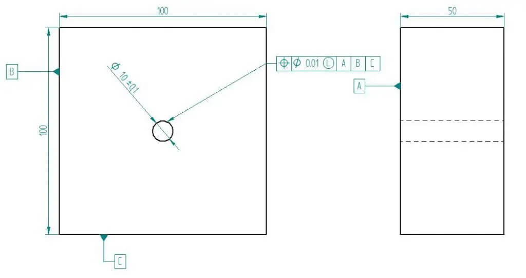
Suppose we want to indicate the true position and positional tolerance of a hole located at the center of a workpiece with dimensions of 100 x 100 x 50 mm (length x width x height) on our drawing. The hole has a diameter of 1 mm with a tolerance of ±0.005 mm.
Choose the type of geometric characteristic
As we are indicating true position in the feature control frame, we will represent it using the assigned symbol of the crosshair (⌖) in the geometric characteristic symbol block.
Choose datum
We begin by selecting the reference datum plane. We can use at least one datum, which can be a point, line, or plane.
In this example, we will select three datum planes and assign names to them in descending order of importance.
Our first datum will be the bottom plane of the workpiece, designated as Datum A. This datum indicates that the axis of the hole must be perpendicular to this plane, ensuring perpendicularity control.
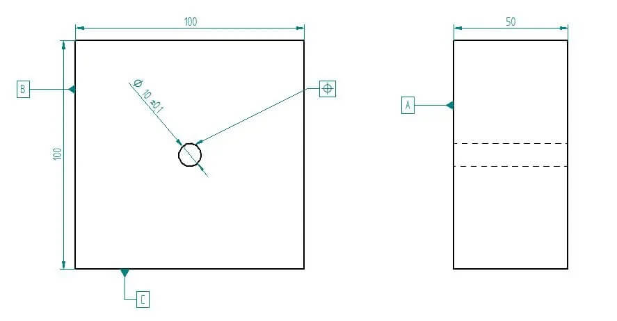
For the second and third datums, we will choose the planes of the left and front face, respectively. We will label these datums as Datum B and Datum C on the engineering drawing.
Next, we will specify the distance of the hole feature from Datum Planes B and C on the drawing. In this case, both distances are 50 mm since the hole is located at the center. These distances are shown as basic dimensions and enclosed in a box to convey the same information.
In the feature control frame, we will write down Datum A, B, and C in the 3rd, 4th, and 5th blocks, respectively.
Describe the tolerance zone and values
In this example, we will utilize the cylindrical tolerancing zone, which will be represented in the feature control frame using the diameter symbol (⌀).
Additionally, we will indicate the total tolerance width as 0.01 mm (±0.005 mm).
Material condition modifiers
If there are any modifiers related to the material condition, we include them after the tolerance value. A circled ‘M’ represents maximum material condition (MMC), and a circled ‘L’ represents least material condition (LMC). MMC is more commonly used than LMC.
True position tolerance is frequently used in conjunction with a material condition modifier. Parts are toleranced within these limits to ensure that they do not interfere excessively during mating. If interference does occur, it is limited, even when the parts are at their tolerance limits.
For a shaft, MMC represents the largest allowable size (diameter), while for a hole, it represents the smallest allowable size. By ensuring that the MMC of the shaft is smaller than the MMC of the hole in our designs, we can always maintain some clearance between the two.
When we include this modifier in our true position control frame, it indicates that we are applying the tolerances based on the maximum material condition. This ensures that the hole is not too small or the shaft is not too large at any point throughout the depth of the feature. Therefore, with this type of feature control, we can control not only the size and location but also the orientation.
How to Calculate True Position?
The true position feature has multiple applications, but it can be a bit complex when it comes to inspection. Let’s begin by understanding how to calculate the position of a manufactured part in relation to the true position of the feature.
The true position is determined using the following formula:
True Position = 2 x SQRT[(Measured X – True X)^2 + (Measured Y – True Y)^2]
Where,
Measured value refers to the reading obtained from measuring instruments
True value represents the true position indicated by basic dimensions
These calculations can be performed using a simple calculator or by manual calculation, as it essentially involves doubling the value of the hypotenuse obtained from applying the Pythagorean theorem.
Ways to Measure True Position
If the calculated value falls within the specified range, we consider the part to be acceptable. There are multiple methods available for conducting these measurements. Let’s explore these options.
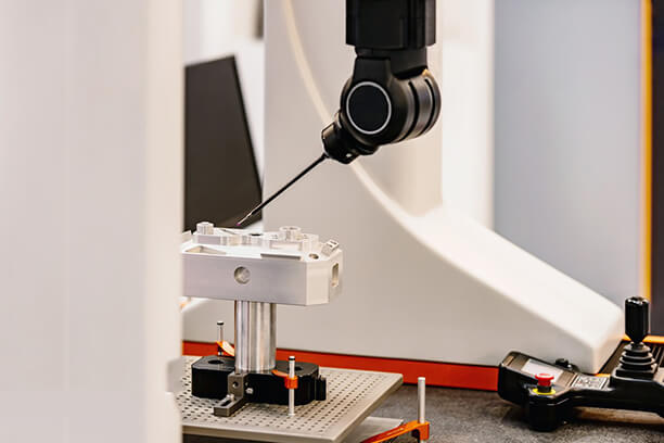
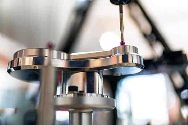
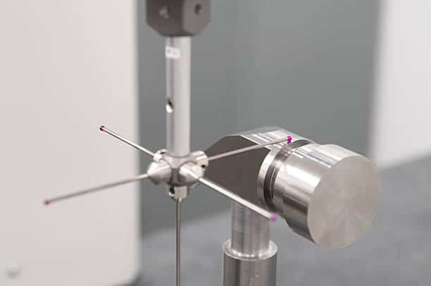
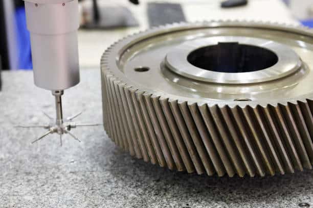
1. Coordinate Measuring Machine (CMM)
CNC machines in machine shops are typically equipped with a CMM that provides highly accurate measurements. These CMMs digitally measure the parts and perform all calculations.
The CMM is considered the most precise method for measuring true position. It consists of a robotic arm with a ball at the end. We maneuver the ball to the specific feature we want to measure. The CMM then traces the feature and converts the motion into the feature’s profile using specialized software.
The measurement process can be somewhat complex. To assist with this, we have outlined a set of general steps that can be helpful. When using a CMM, we typically follow these steps to perform the measurement:
Determine your datum
Refer to the print to identify and locate the specified datum. For instance, let’s assume that Datum A is a datum surface, Datum B is a datum axis, and Datum C is a datum origin.
Align the part
Ensure that the plane is level, and adjust it accordingly. Rotate the part to align with the designated line and set the origin point as the C datum.
Measure features
Identify the dimension indicating the true position and measure it.
Dimension position
Start by clicking on “Dimension” and choose the “Position” option. Then, proceed to report it.
If you’re using feature control frames, it’s necessary to define the datum in the editor before selecting the features you wish to report.
2. Special Caliper
We can use a specialized set of calipers called the center distance digital caliper to measure position. This type of caliper can determine the center distance between two holes or stepped holes. It is capable of measuring various hole center sizes.
This caliper can be used for both step and external measurements. It’s designed with user-friendly features such as locking mechanisms, fine adjustment capabilities, and data presetting functions.
3. Fixed functional gauge
This method is often considered the quickest way to measure true position. It is commonly used in high volume manufacturing processes due to its efficiency. A functional gauge is specifically designed to measure the position and not the size of the feature.
For example, when measuring the true position of a hole on a workpiece: The functional gauge consists of a block with a protruding pin placed at the true position of the hole. The gauge also includes other features that align with the datum. If the pin can enter the hole when the gauge is aligned with the datum, the part is accepted. However, note that measuring the feature size needs to be done separately.
Conclusion
To summarize, the true position represents the precise location of a feature based on basic dimensions, while the position symbol denotes the positional tolerance, which is the acceptable amount of deviation of that feature from its true position.
Custom Precision CNC Machining Services – Runsom Precision
Machining parts is not a task that can be entrusted to just anyone. You need experienced experts who have extensive knowledge in the manufacturing industry. That is why Runsom Precision is the ideal choice for your needs.
Our strong manufacturing capabilities and strict quality control measures ensure that we meet the high tolerance requirements of customers across various industries. Moreover, we conduct a thorough dimensional inspection before delivering the final product.
We understand that you value efficiency, which is why we offer instant quoting and fast lead times. At Runsom Precision, we strive to provide the best solution at a reasonable price beyond your expectations. Request an instant quote today to get started with your project today.
Other Articles You May Be Interested in: