
It is fundamental to have a solid understanding of the technology’s foundations before deciding whether or not to use a new manufacturing method. That is to say, you need to get acquainted with what it is, how it operates, and the different benefits that it offers. The fundamentals of sheet metal fabrication will be discussed in this piece. We will shed some light on this method of producing metal, which has many applications across different sectors.
What Is Sheet Metal Fabrication?
Fabricating objects and structures out of flat metal sheets is what we mean when we talk about sheet metal fabrication. Creating various components and pieces from multiple sheet metals is often the end goal of the processes used to treat sheet metal. Because of this, it is beneficial to conceive of this metal forming procedure not as a special manufacturing process but rather as a collection of different techniques for forming.
These processes often collaborate to generate the necessary component successfully. Cutting, bending, stamping, punching, welding, and finishing are the fundamental processes involved in manufacturing sheet metal products. In a little while, we shall get into the specifics of each of these methods.
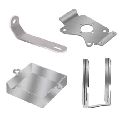
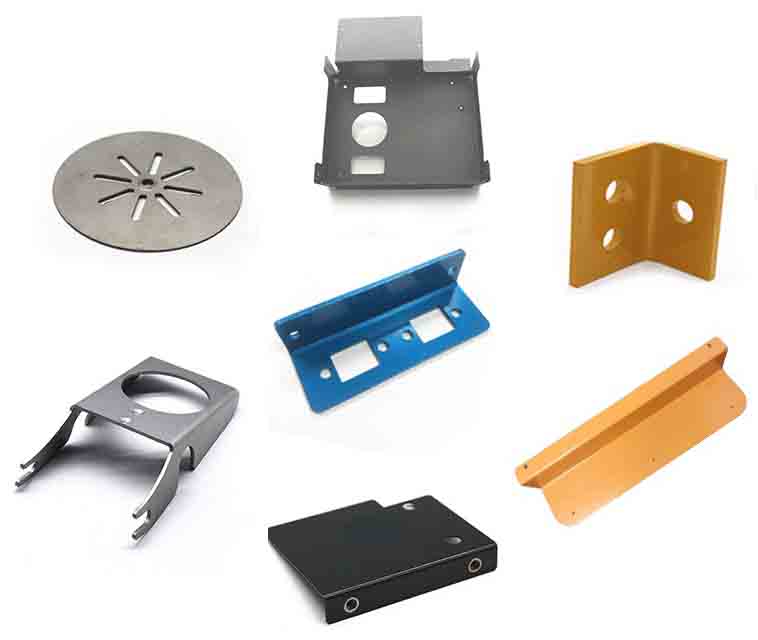
Manufacturing using sheet metal may be applied to various types of metal. Components consisting of aluminum, steel & stainless steel, copper, and brass are just some of the sheet metal products manufactured at our facility. Because of the prevalence of the manufacturing process, it is quite improbable that you will go about your day without interacting with a sheet metal-produced product. You may locate these things almost everywhere. They can take the form of large household appliances or more minute components like brackets or casings.

A Step-by-Step Guide to the Design Process for Sheet Metal
It is common for individuals not to understand the fundamental procedures involved in manufacturing sheet metal. When essential information is lacking, it may be challenging to formulate needs and expectations for a project grounded in reality. Methods for processing sheet metal sometimes entail a series of stages, each of which calls for the participation of a different set of specialists and specialized equipment.
The following steps make up the whole of the design process for metal fabrication:
The Concept

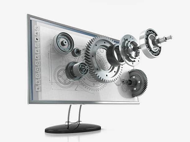
Every step of the rapid prototype starts with a concept, and the sheet metal design is no different. It begins with fundamental ideas about what you want to achieve as a designer. You might jot these ideas down in a preliminary outline to establish realistic criteria for your project. It may also require creating a three-dimensional model of the sheet metal component sought. The model will often include specifications like wall thicknesses, bend curvatures, hole orientations, bend allowances, and more.
Creating Engineering Drawings
After a 3D model has been finished, the next step in the manufacturing process is to develop the necessary drawings. Creating blueprints is essential for engineers to complete before any work can begin. Using these blueprints, the requirements of the sheet metal that will be required to produce the first drawings will be determined.
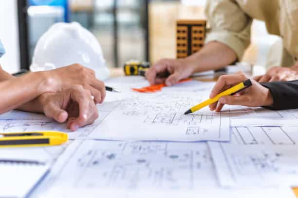
The machine shop will work off of the drawings that have been provided. The drawings typically contain all of the details necessary for manufacturing, such as the choice of materials and the surface finishing, among other things.
Analysis of the Capability to Be Manufactured
In addition to related calculations, the drawings will be crosschecked to verify that they adhere to the prerequisites and criteria. Following a DFM approach helps to concentrate on refining the designs and potentially reducing part counts. An analysis of this kind advises standardizing components for use in various applications.
Engineers will also have a better understanding of how to create designs that are simple enough to be readily built. Once the manufacturability study is complete, there will be a finalized shop design with in-depth computations of stress, strain levels, and load constraints. The procedure for fabricating sheet metal will be decided based on the information accessible there.
The Development of a Prototype
After creating a sheet metal design model, engineers go through several operations to preserve the component’s geometric integrity. Cutting, bending, stamping, punching, and welding are all examples of these processes. Applying surface treatments to the newly produced prototype may also increase the aesthetic value. It is essential to complete each of these stages in the sequence. Suppose you rush through the process steps or omit any of them. In that case, the quality and consistency of the finished product may suffer.
Evaluation of a Prototype
Following the development of the prototype, the customers will evaluate it to confirm that it satisfies their needs. It’s possible that the testing will also entail using such components in realistic settings. In addition, users’ input on the products might be included in the review process.
Production on a Large Scale
For a prototype to enter full-scale manufacturing, it must first be put through a series of tests and satisfy certain specifications.
Techniques for the Fabrication of Sheet Metal
It is crucial to understand the various sheet metal fabrication techniques available to fully comprehend the process of forming multiple components utilizing sheet metal. The processing procedures for sheet metal make the transformation of two-dimensional metal sheets into three-dimensional, functional pieces. The following list contains the most popular techniques for treating sheet metal.
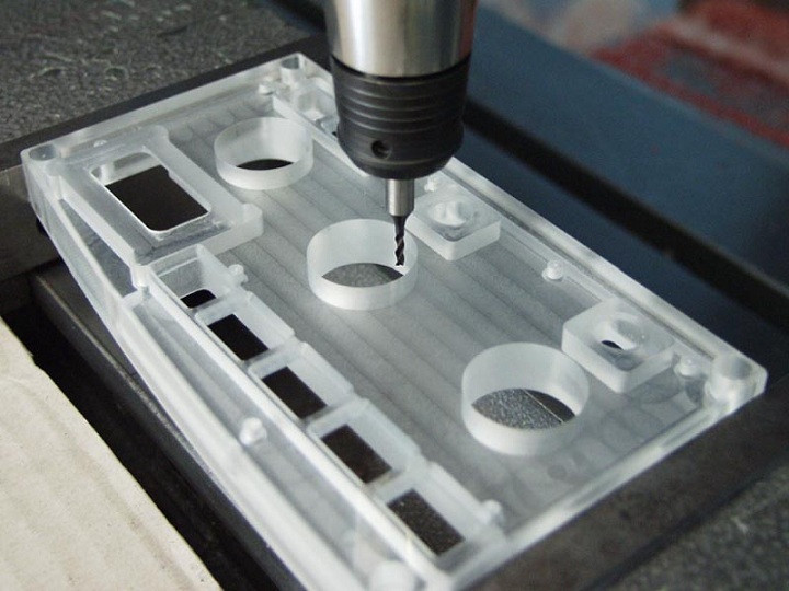
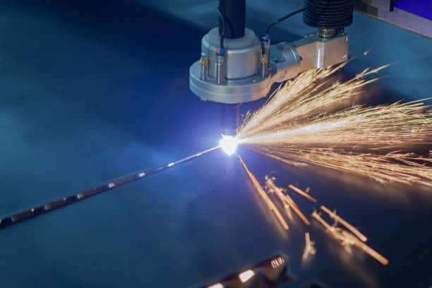
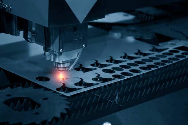
Cutting
Cutting is often performed as the initial stage in manufacturing sheet metal. Cutting the metal sheet is included in this process, as is evident from the activity’s moniker. In other words, the manufacturing process begins with a rectangular metal sheet. After that, the material is cut to size according to the component design provided by the client. Cutting sheet metal may be accomplished in several different ways.
By illustration, a shear is a useful tool for cutting through metal sheets. This is because it employs shear forces to cut. Shearing, punching, and blanking are the three distinct approaches to carrying out this cutting. On the other hand, fabricators can also cut without needing shears. When it comes to industrial projects that need precise cutting and shorter lead times, this is the method that works best.
Stamping
Stamping is a cold-forming process in which flat metal blanks are transformed into various shapes using a pressing action. The procedure calls for the utilization of a tool and die, both of which, when subjected to an impact, alter the shape of the metal by applying shear pressure.
Within the realm of sheet metal fabrication, stamping is a more general phrase. It includes bending, punching, and embossing as well as other processes. Flanging is also a part of it, which involves swiping the sheet of metal in a manner as to make flanges.
Bending
Bending sheet metal is another important phase in the production process. Bending the metal sheets is what this process is all about, as the name suggests. Sheet metal is bent by metal fabricators utilizing a variety of machinery and tools, including press brakes, rolling equipment, and other machinery. Standard shapes like U-bends and V-bends are formed by the sets of equipment used.
Bending is a somewhat difficult procedure that calls for a manufacturer with a high level of expertise, even though to the inexperienced eye, it may seem to be quite easy. The phenomenon known as “spring back,” occurring when a metal object that has been bent attempts to return to its original flat form, is mostly to blame for this phenomenon. For operators to solve this difficulty with sheet metal manufacturing, they have to overbend the component so that its spring-back angle matches the angle they want.

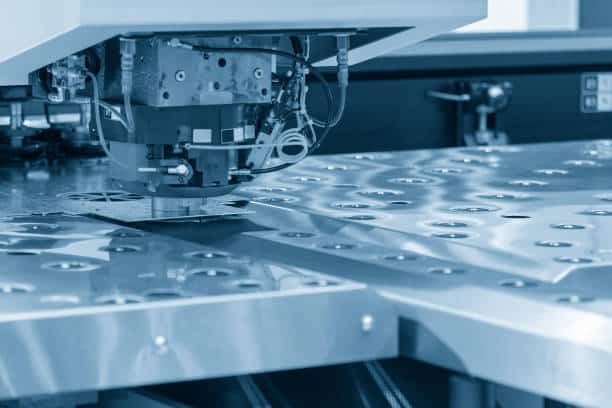
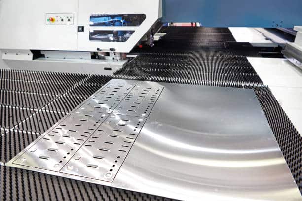
Punching
Punching is a method used to produce holes in a sheet of metal. This approach uses a punch-and-die combination (made from a hard metal). The materials use shear force to puncture holes into the metal sheet. After that, the scrap material that was generated by the hole is collected by the die. Making an indentation in the metal sheet may also be accomplished by punching.
Welding
One of the last steps in sheet metal manufacturing is the welding process. The fundamental function of fusing many pieces of metal into a single unit is “sheet metal welding.” Stick welding, TIG welding, and MIG welding are some of the many types of welding that may be performed.
Even though their methods are distinct from one another, all three are meant to join pieces of metal together by heating the edge of the component and then adding filler. It creates a metallurgical connection between the elements, which fuses them more securely. Welding is only required when a product consists of not one but two or more individual parts.
Selection of Sheet Metal Fabrication Materials
Sheet metal engineering makes use of a diverse assortment of different kinds of materials. It is essential to pick the most appropriate decision for your product to guarantee the highest possible quality.
Your decision should be based on the outcome you want and your general expectations for it as a whole. The following are examples of sheet metal materials that are used in fabrication:
- Stainless Steel: You have a few different options regarding the kind of stainless steel available. They can be austenitic stainless steel. These would be non-magnetic metals that include significant amounts of nickel and chromium. As a result of their ability to withstand corrosion and malleability, they find widespread use. On the other hand, ferritic stainless steel has a magnetic property. They work well in situations that do not need structural support or are aesthetic.
- Hot Rolled Steel: Steel created via several rolling operations at temperatures more than 1700 degrees Fahrenheit is referred to as hot-rolled steel. Because of their malleability, steels of this kind may be readily shaped into substantial chunks.
- Cold Rolled Steel: Steel that has been cold rolled has been hot-rolled steel that has undergone further processing. They have a higher tolerance and provide a smoother experience overall.
- Pre-Plated Steel: Materials of this kind are also known as galvanized sheet metal and go by that name. They are protected from rust by a coating that is applied during manufacturing. Because of their enhanced flexibility, they also facilitate processing technologies that are less labor-intensive for sheet metal.
- Aluminum: It is another material that is often used in production settings. It has a great strength-to-weight ratio for something of its size. In addition, it has a wide variety of properties that enable it to fulfill the prerequisites of various applications.
- Copper and Brass: Because brass contains less zinc, working with brass is simpler. Copper metals naturally have oxide layers that serve as a protective barrier against corrosion. Because of their visually pleasant appearances, both materials are suitable for use in architectural items.
Choosing the Appropriate Surface Finish for Sheet Metal Fabrication
Surface finishing is an additional crucial step in the process of fabricating bespoke sheets of metal. The surface treatments of the metal offer advantages, both aesthetically and realistically speaking.
Sheet metal may have a variety of surface treatments applied to it, including the following:
- Sand Blasting: This technique includes using high-velocity projectiles to spray sand or other abrasives on the sheet metal to smooth it. Therefore, it imparts a matte texture to the sheet metal to prepare it for coating.
- Buff Polishing: This technique involves using a cloth wheel to buff the surface layer, which ultimately results in the metal having a glossy appearance.
- Powder Coating: It is a process that includes spraying powdered paint directly onto the surface of the metal component. After this, a coating that is resistant to wear is created on the element by baking it in an oven.
- Anodizing: The process of anodizing a component provides it with superior rust resistance capabilities. Additionally, it strengthens both the surface’s hardness and its durability.
- Chemical Films: These are types of coatings that are known for their high conductivity and resistance to corrosion. The result of this coating procedure is a surface that has a golden sheen, and it works best as a basis for paint.
Implications of Design on Sheet Metal Fabrication
When modeling a sheet metal component, some of the most critical design characteristics to take into consideration are as follows:
- Wall Thickness: Maintaining a uniform thickness across any geometry is of the utmost importance. Sheet metals of varying thicknesses will need to be used to fabricate geometries with more than one wall thickness. As a result, aligning and orienting the pieces may provide erroneous results or need more time.
- Bend Radii: The inner bend radius of sheet metal must be maintained at a minimum value equivalent to the material’s thickness. Because of this, distortions and inequalities in the final components will be less likely to occur. The element’s cost-effectiveness and appropriate alignment are ensured by maintaining the bend radii uniformly throughout the section.
- Bend Allowance and Deduction: Bend allowance is the amount of material that must be added to the actual lengths of the pieces to assist in developing a flat design. The deduction is the opposite of bend allowance. The term “bend deduction” refers to the amount of material that must be subtracted from the length of the flanges to achieve a flat design.
- K Factor: The ratio of the thickness of the material to the neutral axis is referred to as the K factor. The K factor is used in the sheet metal process. This number varies depending on the different physical features of the materials being utilized and their thickness.
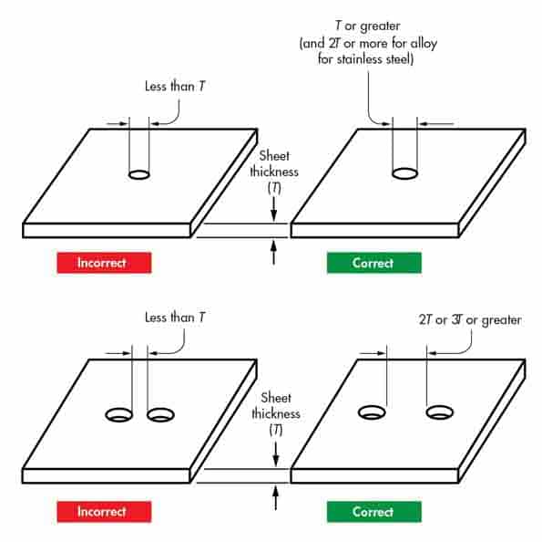
- Holes and Slots Orientation: Both of these elements are quite essential in their own right. It is recommended that the diameter of any holes or slots be equal to the thickness of the sheet metal. In addition, the holes have to have appropriate margins between them. They shouldn’t be positioned in such a way that brings them too near to the edge of the material.
Hems, notches, tabs, spirals, fillets, and countersinks are some of the other consequent effects that should be considered.
A Few DFM Tips for Sheet Metal Fabrication
To create components more efficiently and effectively, it is essential to know some useful design ideas for sheet metal fabrication.
When designing with sheet metal, it is essential to describe the hole sizes, alignment, and positions precisely. If the hole sizes are less than the thickness of the sheet metal, the burnishing process may take longer, the punch loading may be higher, and the burr may be excessive. Because of this, the diameters of the holes should be larger than the thickness of the sheet metal.
In addition, the space between holes has to be at least twice as far as the thickness of the sheet metal. In circumstances where a hole must be located close to the edge, the distance between that hole and the border must be equal to the thickness of the sheet.
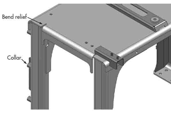
Sheet metal components may be strengthened using collars and bend relief around pierced locations. To prevent fractures in parts that include tabs or lugs, grain structures are another factor that must be considered. Lugs should not run in a direction that is parallel to the grain. It may cause the surface to break as a result. Instead, they should get aligned perpendicular to the grain direction or somewhat less than 45 degrees in that direction.
The clearances between punch and die should be kept relatively wide to prevent the punch from wearing down too quickly. Additionally, adding beads to bends and chamfers to corners makes the material more rigid. You may lessen the impact of the spring-back effect in this manner. While coining across flared holes, a sheet metal object may keep its flatness and strength without further work.
Sheet Metal Fabrication
Fabricating something out of sheet metal combines aspects of both science and art. Because of the wide variety of subtleties and methods involved, working with a qualified metal fabricator on every job is essential. Since you have a basic understanding of sheet metal design, you should outsource the remainder of the work to a professional firm.
Custom Sheet Metal Fabrication Services at Runsom
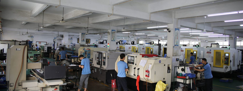
Runsom employs sheet metal technology to bend, punch, and cut standard gauge metals for both rapid prototypes and low to high-volume production runs. What set us apart from other conventional sheet metal shops is our incredible capacity and proficiency in sheet metal manufacturing of end-use and durable metal parts or components coupled with broad material selections and finishes matching your needs.
From prototypes to assemblies to finishing options, Runsom always keeps you traceable with your order and concentrates on every single detail and matter on model designs, user experience online, and each production stage.
If you want to designate a customized metal sheet for your applications, please contact us or just specify it in your sheet metal quotation.
Other Articles You May be Interested in: