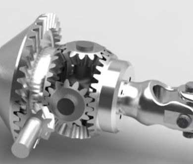
DMLS is a rapid manufacturing process, as metal additive manufactured parts are applied in various industry areas. Its great design freedom, component simplification and consolidation are best suitable for custom or medium volume parts production.
DMLS printing process
DMLS is a powder fusion technology, which use laser system to fuse metal powder layer by layer. Each layer or slice is parts cross-section geometry in certain height, these layers and slices contain together to be the entire part. Finite thickness metal will exposure to laser system for sintering process, then repeat these process as all layers are finished. As laser fuses metal powders, current layer will also fuse to previous layers. Parts size and printer parameters will determine production time.
As a typical DMLS machine, the laser system scan top power surface bed, sintering powder to bonded cross-sectional slice with certain height. The build platform decrease lower after sintering, then recoated blader sweep across powder bed with a new layer of metal powder. Collecting platform reduce lower to accommodate overflow powder. This process repeats until final parts are completed, which consist of thousands of micron thickness layers.
After fabrication process, we need band saw or wire EDM to remove finished parts form build platform after loose powder is brushed away.
DMLS designing
There are several design recommendations in DMLS designing process, these principles will assist us achieve high quality, excellent surface finish and high dimension accuracy. Although most design guidelines depends on printing materials and laser parameters, geometric recommendations will guarantee design part produce as expectation.
General guideline for DMLS designing
Wall thickness: For most metal materials, minimum wall thickness of 0.4mm will ensure success DMLS printing process .
Pin diameter: The minimum pin diameter of 1mm is reliable, while smaller diameters will reduce contour sharpness.
Hole size: Holes diameter between 0.5mm and 6mm can be created reliably without additional support. Orientation determine support free of holes diameter in 6mm to 10mm. Greater than 10mm diameter holes need support structures.
Escape hole: hollow metal parts need escape holes to remove loose metal powder, recommended hole diameter is 2-5mm. Multiple escape holes will improve powder removal efficiency.
Overhangs: the minimum overhangs angle without support is 45 degrees in most case.
Unsupported edges: the maximum length of cantilever overhangs is 0.5mm, horizontal overhangs with support on both sides can reach to 1mm.
Aspect ratio: the maximum ratio of vertical height to section is 8:1, which will ensure stability of printing parts on build plate.
Tolerance: tolerance on printing direction is ± 1 layer thickness, on x-y direction, achievable tolerance is ± 0.127mm.
Support material
In reason of high temperatures in DMLS process and its natural layer by layer construction, we need support structures to connect unsupported geometry to build platform, and also work as thermal heat sink. Support material play essential roles in DMLS designing, there are two factors we need to consider as following:
- DMLS sinter layers of metal powders at high temperature, each layer need solid thing to build upon rather than loose powder in SLS. To achieve this, support structures will be printed firstly, then solid sections can be built on top of these, which are not attached to build plate.
- Different cooling process in each layer will create residual stress, which will result to curling and distorting. Support material will draw heat away form recent printed sections, and also anchor them on solid base.
Support material will add extra cost and need to be removed when printing process finish. In addition, post-processing on support material contact surface need to reach same surface finish on unsupported area.
Surface quality
As in designing process, we need presentation side surface to be smooth, so post-process is required. We need some steps to improve surface quality with part orientation selection.
- Upward facing surfaces have sharper edges and better surface quality than downward facing.
- In order to avoid stepped effect on surface, the angle of plane should be greater than 20 degree relative to horizon.
Process limitations
Cost
The cost of DMLS materials are very high, so traditional manufacturing technology may be more cost-effective, especially in large scale production. DMLS is most suitable for complex and custom parts manufacturing or special geometries cannot be produced by traditional method.
Design for additive manufacturing
There is a misconception for DMLS, which is any applications design for conventional manufacturing can be converted to DMLS solution. If parts is designed for conventional manufacturing, it is not suitable for 3D printing. If a part has large size to complexity ratio without additional value or functional capability, it can be design for DMLS.
Product size
DMLS produce smaller part volume compare to traditional technology, its average volume is 250 mm x 250 mm x 300 mm.
Machine complexity
DMLS machine is not plug-to-play as polymers system, most of DMLS machines are industrial size, which need strict operation, material handling, post-processing and maintenance procedures.
Conclusion
In DMLS designing process, support is critical factor to optimize geometry and placement, save cost and time. Part orientation is considered for sharper edges and better surface finish.


