
Identifying the appropriate thread type is critical for the optimal performance of your equipment. Pneumatic components such as air preparation units, air cylinders, and valves, are fitted with specific port threads, and selecting the correct thread type guarantees maximum compatibility with your equipment. Even though threads may appear similar at first glance, subtle variances can make them incompatible with one another. For instance, G threads cannot be used with NPT threads due to differences in their angles, shapes, and thread pitches (i.e., threads per inch).
To help you recognize the thread type, we conclude with a straightforward, step-by-step guide. Additionally, we’ll discuss some of the most common port thread types, such as NPT/NPTF, BSPP (aka G), BSPT (aka R), PT, Metric (M), and SAE and we also provide dimension charts of these thread types for reference.
Basics of threads
There are many variations in different types of threads. The fundamental aspects of threads are explained below.
Design
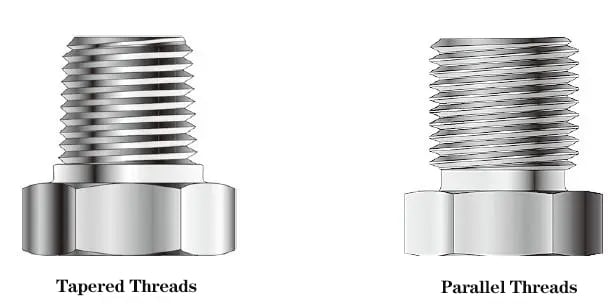
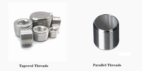
Distinctions between parallel and tapered thread designs can help to identify the type of thread, as seen in the image below.
Gender
Male and female are the terms used to describe a matched pair of threads, one external and the other internal. A screw, for instance, is equipped with male threads while the corresponding hole has female threads.
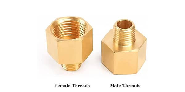
Male Threads v. Female Threads
The location of the threads can show whether the thread type is male or female. If they are situated on the exterior of the thread, it is a male thread. Conversely, if the threads are located on the interior of the thread, it is a female thread. It is worth noting that the gender of the thread does not necessarily affect its performance. Its purpose is solely to differentiate between the two connections.
Handedness
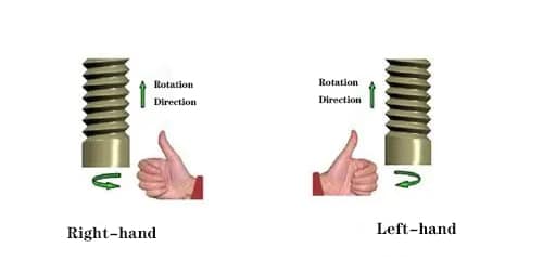
A thread helix can twist in two directions, and when viewed from the axis passing through the center of the helix, most threads appear to move toward the viewer when turned in a counter-clockwise direction and away from the viewer when turned clockwise.
As per convention, right-handedness is considered the standard for screw threads, and thus, most fasteners and threaded parts come with right-handed threads.
Angle
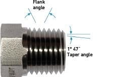
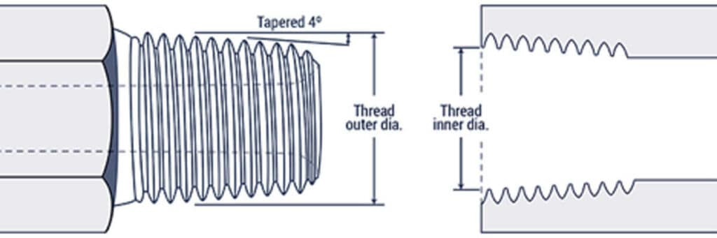
The flank angle of a screw thread refers to the angle formed between the flank of the thread and the line perpendicular to the screw’s axis. On the other hand, tapered threads feature a taper angle, which is the angle formed between the taper and the center axis of the pipe.
Diameter
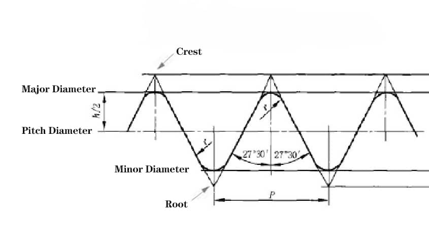
- The thread tips are used to determine the major diameter.
- The groove of the thread is what determines the minor diameter.
- The pitch diameter is either the distance between the tips of two opposite flanks or the length of the centerline of the profile.
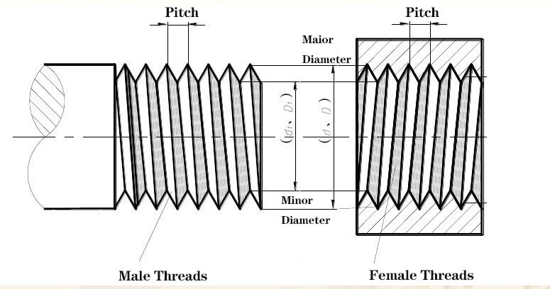
Pitch/TPI
The pitch of a thread is measured as the distance between one thread crest and the next, expressed in millimeters (mm). For inch threads, TPI (threads per inch) is used as a unit of measurement.
Crest/Root
The crest refers to the outermost part of a thread, while the root refers to the innermost part of the thread.
Available Tools for Identifying Thread
To ensure precise measurements of commonly used connectors, it is essential to have the necessary tools such as a seat angle gauge, thread pitch gauge, and an ID/OD caliper before starting the identification task.
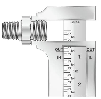
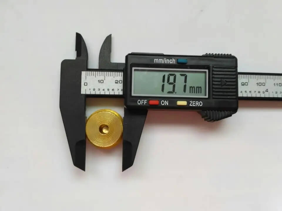
Thread ID/OD Caliper
A caliper is a suitable tool to measure the diameter of a thread. The outside diameter of a male thread and the inside diameter of a female thread can be measured using a caliper. For more experienced users, digital calipers are available from various retailers, which can save time and make the process easier.
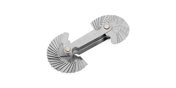
Thread Pitch Gauge
The purpose of a pitch gauge is to determine the space between thread crests. The gauge is used to measure the number of threads per inch for NPT, UN/UNF, BSPP, and BSPP. In the case of metric threads, the pitch gauge calculates the distance between each crest in millimeters.
Seat Angle Gauge
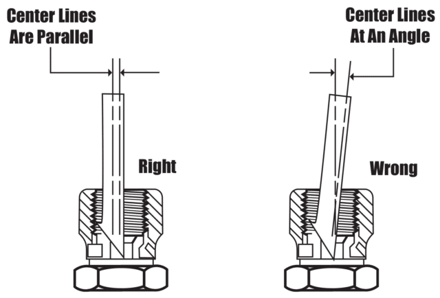
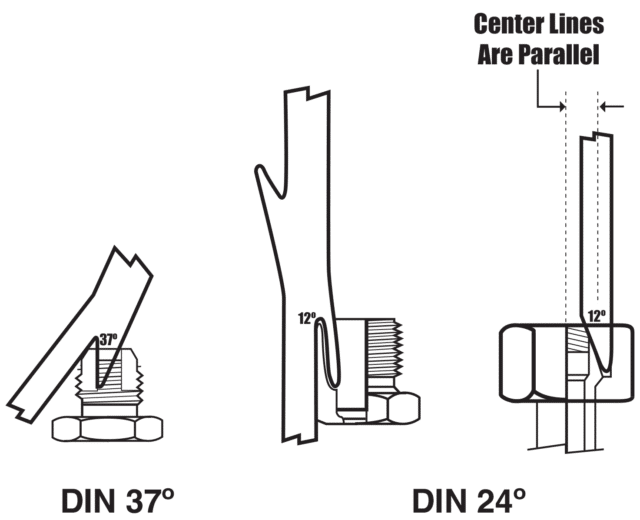
When dealing with angled port connections, it is essential to utilize a seal angle gauge to determine the appropriate seat angle. For female connections, insert the angle gauge into the connection and place it on the sealing surface. The correct angle is determined when the connection and gauge are parallel. For male connections, place the gauge on the sealing surface and determine the correct angle when the center lines of the connection and gauge are parallel.
To measure the seat angle, refer to the seat gauge and follow the given illustration. Align the centerline of the seat gauge with the projected longitudinal axis of the coupling to ensure that the gauge and seat angles are identical.
Please take note that using different thread configurations may result in thread binding. Therefore, it is important to avoid mixing thread configurations.
How to Identify Types of Threads?
In this part, we offer a straightforward, step-by-step guide to help you recognize your thread type.
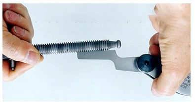
Step 1 – Determine if the thread is parallel or tapered
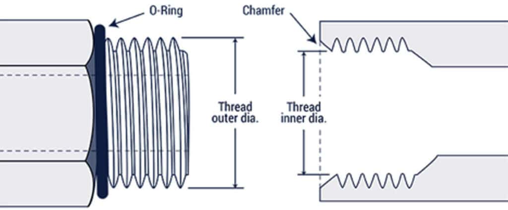
Visual inspection alone can suffice in some cases to complete the first step. When it comes to tapered threads, the diameter of the fitting decreases towards its end, while parallel threads maintain a consistent diameter throughout. If the difference is not apparent by examining the fitting, utilize the parallel jaws of a caliper to distinguish. Moreover, the existence of an O-ring or the elimination of a tube nut is typically a sign that the male thread is parallel.
Step 2 – Determine the pitch size
The size of the pitch can be determined by using a pitch gauge to make a comparison or by precisely measuring and calculating the number of threads within a specific distance. It is more convenient to perform this task using a pitch gauge against a lighted background. Since some thread pitches are quite similar, it is recommended to experiment with several gauges to find the most suitable one. The outcome of Step 2 will further reduce the potential thread forms as most have a unique pitch.
Examine the table below for the typical pitch sizes associated with each of the various thread types.
| Thread Type | Pitch Size |
| BSPP (British Pipe) | 11, 14, 19, 28 |
| BSPT (British Pipe) | 11, 14, 19, 28 |
| Metric Parallel | 1.0, 1.5, 2.0 |
| Metric Tapered | 1.0, 1.5, 2.0 |
| UN/UNF (SAE) | 12, 14, 16, 18, 20, 24 |
| NPT/NPTF (American Pipe) | 11 ½, 14, 18, 27 |
Step 3 – Determine the thread size
Combining Steps 1 and 2 helps predict the correct procedure for Step 3. To determine thread size, use either of the two methods based on whether it’s a pipe or a non-pipe thread. Remember that tapered threads may not necessarily be pipe threads and pipe threads can be parallel. For pipe threads, compare the size with a nominal size profile in the left photo. For non-pipe threads, use a caliper to measure the major diameter as shown in the right photo. A useful tip for pipe sizes up to 2″ is to measure the outside diameter, subtract 1/4″, and round off.

Step 4 – Determine thread standard
The last step of the process involves using a standardized format to indicate the type of thread for others to comprehend. Various thread types standards such as NPT, PT, and G exist, and they usually include information about the thread size (either nominal or actual), the type, and, in some cases, the pitch.
We combine and simplify the four steps above into a table in the following and provide examples for each thread type, so you can easily follow the steps and then determine the thread type.
| Thread Type | STEP 1. Tapped or Parallel | STEP 2. Thread Pitch | STEP 3. Thread Size | STEP 4. Thread Standard |
| BSPP | Parallel | 11, 14, 19, 28 | Compare with profile | G size-pitch e.g.G1/8-28 |
| BSPT | Tapered | 11, 14, 19, 28 | Compare with profile | R, size-pitch e.g.R1/2-14 |
| Metric Parallel | Parallel | 1.0, 1.5, 2.0 | Use caliper | M, size × pitch e.g.M14×1.5 |
| Metric Tapered | Tapered | 1.0, 1.5, 2.0 | Use caliper | M, size × pitch, keg or Taper e.g.M10 × 1 keg or Taper |
| UN/UNF (SAE) | Parallel | 12, 14, 16, 18, 20, 24 | Use caliper | Size-pitch, type e.g.3/4-16 UN/UNF |
| NPT/NPTF | Tapered | 11 ½, 14, 18, 27 | Compare with profile | Size-pitch, type e.g.1/4-18 NPT |
Standards for Thread Types
First, let’s understand some common abbreviations for thread standards and learn their full names.
| Abbreviation | System Name |
| BSP | British Standard Pipe |
| BSPP | British Standard Pipe Parallel |
| BSPT | British Standard Pipe Taper |
| UNC | Unified National Coarse |
| UNF | Unified National Fine |
| UNEF | Unified National Extra Fine |
| NPT | National Pipe Taper |
| NPTF | National Pipe Taper Fuel |
These tables and images provided below can aid you in selecting the appropriate thread type that meets your requirements.
BSP Thread Type – British Standard Pipe
BSP is a globally accepted thread type utilized for connecting and sealing pipe ends, particularly in Europe. It comprises two variants: BSPP, which refers to parallel or straight threads, and BSPT, which pertains to tapered threads. Occasionally, G threads are used to denote BSPP threads, while R threads are used for BSPT threads.
| Dash Size (Imperial Size) | Thread Pitch | Male Thread O.D. | Female Thread I.D. | ||
| mm | inches | mm | inches | ||
| -02 (1/8) | 28 | 9.7 | 0.38 | 8.9 | 0.35 |
| -04 (1/4) | 19 | 13.2 | 0.52 | 11.9 | 0.47 |
| -06 (3/8) | 19 | 16.5 | 0.65 | 15.2 | 0.60 |
| -08 (1/2) | 14 | 20.8 | 0.82 | 19.1 | 0.75 |
| -10 (5/8) | 14 | 22.4 | 0.88 | 20.3 | 0.80 |
| -12 (3/4) | 14 | 26.4 | 1.04 | 24.6 | 0.97 |
| -16 (1) | 11 | 33.0 | 1.30 | 31.0 | 1.22 |
| -20 (1 ¼) | 11 | 41.9 | 1.65 | 39.6 | 1.56 |
| -24 (1 ½) | 11 | 47.8 | 1.88 | 45.5 | 1.79 |
| -32 (2) | 11 | 59.7 | 2.35 | 57.4 | 2.26 |
*O.D. = Outside Diameter, I.D. = Inside Diameter
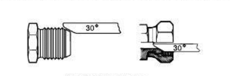
BSPP Thread Type – British Standard Pipe Parallel
The male end of BSPP has a seat of 300, which is sealed by the tapered nose of the female swivel. Although the male end is similar to the NPSM male, they cannot be interchanged because of their different thread pitches.
| Dash Size (Imperial Size) | Thread Pitch | Male Thread O.D. | Female Thread I.D. | ||
| mm | inches | mm | inches | ||
| -02 (1/8) | 28 | 9.7 | 0.38 | 8.9 | 0.35 |
| -04 (1/4) | 19 | 13.2 | 0.52 | 11.9 | 0.47 |
| -06 (3/8) | 19 | 16.5 | 0.65 | 15.2 | 0.60 |
| -08 (1/2) | 14 | 20.8 | 0.82 | 19.1 | 0.75 |
| -10 (5/8) | 14 | 22.4 | 0.88 | 20.3 | 0.80 |
| -12 (3/4) | 14 | 26.4 | 1.04 | 24.6 | 0.97 |
| -16 (1) | 11 | 33.0 | 1.30 | 31.0 | 1.22 |
| -20 (1 ¼) | 11 | 41.9 | 1.65 | 39.6 | 1.56 |
| -24 (1 ½) | 11 | 47.8 | 1.88 | 45.5 | 1.79 |
| -32 (2) | 11 | 59.7 | 2.35 | 57.4 | 2.26 |
BSPT Thread Type – British Standard Pipe Taper
A tapered female is mated with a tapered male of BSPT and the threads are used for sealing. Even though the BSPT male end is comparable to NPTF, the two cannot be substituted due to their varying thread sizes and forms.
Note that the JIS tapered pipe thread, also known as PT thread, is interchangeable with the BSPT thread.
| Dash Size (Imperial Size) | Thread Pitch | Male Thread O.D. | Female Thread I.D. | ||
| mm | inches | mm | inches | ||
| -02 (1/8) | 28 | 9.7 | 0.38 | 8.9 | 0.35 |
| -04 (1/4) | 19 | 13.2 | 0.52 | 11.9 | 0.47 |
| -06 (3/8) | 19 | 16.5 | 0.65 | 15.2 | 0.60 |
| -08 (1/2) | 14 | 20.8 | 0.82 | 19.1 | 0.75 |
| -10 (5/8) | 14 | 22.4 | 0.88 | 20.3 | 0.80 |
| -12 (3/4) | 14 | 26.4 | 1.04 | 24.6 | 0.97 |
| -16 (1) | 11 | 33.0 | 1.30 | 31.0 | 1.22 |
| -20 (1 ¼) | 11 | 41.9 | 1.65 | 39.6 | 1.56 |
| -24 (1 ½) | 11 | 47.8 | 1.88 | 45.5 | 1.79 |
| -32 (2) | 11 | 59.7 | 2.35 | 57.4 | 2.26 |
PT – JIS Tapered Pipe Thread
The PT thread type and the BSPT thread type can be interchanged as mentioned before. Nevertheless, due to the absence of a 30-degree flare on the male PT thread, it cannot be connected to the BSPP female swivel with a conical seat. To achieve a leak-proof seal, it’s recommended to apply thread sealant when using PT threads.
| Dash Size (Imperial Size) | Thread Pitch | Male Thread O.D. | Female Thread I.D. | ||
| mm | inches | mm | inches | ||
| -02 (1/8) | 28 | 9.4 | 0.37 | 8.1 | 0.32 |
| -04 (1/4) | 19 | 13.7 | 0.53 | 12.4 | 0.49 |
| -06 (3/8) | 19 | 17.2 | 0.68 | 16 | 0.62 |
| -08 (1/2) | 14 | 21.5 | 0.84 | 19.8 | 0.77 |
| -10 (5/8) | 14 | 23.1 | 0.91 | 20.6 | 0.81 |
| -12 (3/4) | 14 | 26.9 | 1.06 | 25.4 | 1 |
| -16 (1) | 11 | 34 | 1.34 | 31.8 | 1.25 |
| -20 (1 ¼) | 11 | 42.6 | 1.68 | 40.4 | 1.59 |
| -24 (1 ½) | 11 | 48.5 | 1.9 | 46.2 | 1.81 |
| -32 (2) | 11 | 60.4 | 2.37 | 58.2 | 2.29 |
Metric Parallel/Tapered Thread
The metric thread type is widely used in Europe and is characterized by a cylindrical inner and outer diameter, precisely measured in millimeters. The fine taper of the metric tapered thread enables optimal force transmission. To identify metric threads in writing, look for a capital “M” followed by the nominal outside diameter (e.g., M22 x 1.5). When measuring pitch size, ensure that you use a metric pitch gauge.
| SI Metric Port Size mm | Thread Pitch mm | Male Thread O.D. | |
| mm | inches | ||
| M5 × 0,8 | .8 | 5 | 0.1968 |
| M8 × 1,0 | 1 | 8 | 0.3150 |
| M10 × 1,0 | 1 | 10 | 0.3937 |
| M12 × 1,5 | 1.5 | 12 | 0.4724 |
| M14 × 1,5 | 1.5 | 14 | 0.5512 |
| M16 × 1,5 | 1.5 | 16 | 0.6299 |
| M18 × 1,5 | 1.5 | 18 | 0.7087 |
| M22 × 1,5 | 1.5 | 22 | 0.8661 |
| M27 × 2,0 | 2 | 27 | 1.063 |
| M33 × 2,0 | 2 | 33 | 1.299 |
| M42 × 2,0 | 2 | 42 | 1.654 |
| M50 × 2,0 | 2 | 50 | 1.969 |
| M60 × 2,0 | 2 | 60 | 2.362 |
SAE Thread Type – Straight Thread O-Ring Boss
The straight threads from the Society of Automotive Engineers (SAE) are capable of sealing due to the presence of a 90-durometer Buna-N “O” Ring, which is dependable and can be reused. SAE straight threads feature cylindrical shapes, are utilized for connecting fluids and gases in hydraulic and pneumatic systems, and are frequently located on hoses and fittings. Unlike other thread types that necessitate the compression of the male and female ends’ threads to create a seal, the O-Ring on this thread type doesn’t require that.
The SAE thread dimension is commonly determined by measuring the major diameter, which refers to the outer diameter of the threaded part of the component or fastener. This major diameter is then utilized to determine the appropriate size of the nut or hole that will be paired with it.
| Dash Size (Imperial Size) | Thread Pitch | Male Thread O.D. | Female Thread I.D. | ||
| mm | inches | mm | inches | ||
| -02 (1/8) | 24 | 7.9 | 0.31 | 6.9 | 0.27 |
| -03 (3/16) | 24 | 9.7 | 0.38 | 8.6 | 0.34 |
| -04(1/4) | 20 | 11.2 | 0.44 | 9.9 | 0.39 |
| -05(5/16) | 20 | 12.7 | 0.5 | 11.4 | 0.45 |
| -06(3/8) | 18 | 14.2 | 0.56 | 12.9 | 0.51 |
| -08(1/2) | 16 | 19 | 0.75 | 17 | 0.67 |
| -10(5/8) | 14 | 22.3 | 0.88 | 20.3 | 0.8 |
| -12(3/4) | 12 | 26.9 | 1.06 | 24.9 | 0.98 |
| -14(7/8) | 12 | 30 | 1.18 | 27.7 | 1.09 |
| -16(1) | 12 | 33.3 | 1.31 | 31 | 1.22 |
| -20(1 ¼) | 12 | 41.4 | 1.63 | 39.1 | 1.54 |
| -24(1 ½) | 12 | 47.7 | 1.88 | 45.5 | 1.79 |
| -32(2) | 12 | 63.5 | 2.5 | 61.2 | 2.41 |
The table provided below shows several standard SAE thread dimensions and their corresponding thread pitches, but note that there are many more sizes available beyond those listed.
| Size (inch) | Thread Pitch | ||
| UNC | UNF | UNEF | |
| 1/4 | 20 | 28 | 32 |
| 5/16 | 18 | 24 | 32 |
| 3/8 | 16 | 24 | 32 |
| 7/16 | 14 | 20 | 28 |
| 1/2 | 13 | 20 | 28 |
| 9/16 | 12 | 18 | 24 |
| 5/8 | 11 | 18 | 24 |
| 3/4 | 10 | 16 | 20 |
| 7/8 | 9 | 14 | 18 |
| 1 | 8 | 12 | 16 |
*UNC – Unified National Coarse, UNF – Unified National Fine, UNEF – Unified National Extra Fine.
NPT/NPTF Thread Type
The tapered outer and inner diameter of this thread type, which is self-sealing, is commonly used in North America. When the flanks of the threads are torqued, they compress against each other, forming a leak-tight seal. Nonetheless, it’s advisable to use PTFE tape or a sealing compound to ensure a completely leak-free seal.
NPTF is a semi-compatible variant of NPT that guarantees an even more leak-free seal. However, it’s crucial to note that combining these variants reduces their leak-proof characteristics. To avoid future disassembly difficulties caused by corrosion, NPT threads must be free of burrs and lubricated with lubricating paste or tape.
| Dash Size (Imperial Size) | Thread Pitch | Male Thread O.D. | Female Thread I.D. | ||
| mm | inches | mm | inches | ||
| -02 (1/8) | 27 | 10.3 | 0.41 | 9.4 | 0.37 |
| -04 (1/4) | 18 | 13.7 | 0.54 | 12.4 | 0.49 |
| -06 (3/8) | 18 | 17.3 | 0.68 | 15.7 | 0.62 |
| -08 (1/2) | 14 | 21.3 | 0.84 | 19.3 | 0.76 |
| -10 (5/8) | 14 | 22.9 | 0.90 | 21.1 | 0.83 |
| -12 (3/4) | 14 | 26.9 | 1.06 | 24.9 | 0.98 |
| -16 (1) | 11½ | 33.3 | 1.31 | 31.5 | 1.24 |
| -20 (1 ¼) | 11½ | 42.2 | 1.66 | 40.1 | 1.58 |
| -24 (1 ½) | 11½ | 48.3 | 1.90 | 46.2 | 1.82 |
| -32 (2) | 11½ | 60.4 | 2.38 | 57.9 | 2.29 |
Conclusion
Before selecting and installing the appropriate hose, tube, or adapter fitting, it is essential to identify the ports and connectors accurately in fluid piping systems. However, this process can be simplified with our guide to thread types identification, making measurement and identification a straightforward task. The knowledge of thread types, their sizes, and their uses can help you choose the best thread for your project and ensure the longevity and durability of your finished product.
Your CNC Machining Expert for Any Types of Threaded Parts – Runsom Precision

The team of engineers and machinists at Runsom Precision has a comprehensive understanding of different types of threads, including tapered and parallel, thread sizes, pitch sizes, and industry standards. We are an expert in the CNC machining industry for over ten years and are committed to offering our customers a perfect solution for their projects. If you have any questions, feel free to contact us or simply submit your 3D files online.
Other Articles You May Be Interested in: